

Interfacing with C plus plus-programing communication with microcontrolers (K. Bentley, 2006)
.pdf8 DRIVING MOTORS - DC & STEPPER 225
computer would take to complete 256 writes to the port. Depending on the desired duty cycle, a portion of the 256 writes to the port can be used to send 0x09 to the port (see Table 8-8) to turn the motor on in the forward direction. The remainder of the writes can send 0x00 to the port to turn the motor off. For example, if we want 50% duty cycle, we will output 0x09 to the port for the first 128 writes and output 0x00 to the port for the remaining 128 writes. This is a means to control the speed of the motor. A number between 0 and 255 (forming 256 different speed settings) can be used to specify the speed. Figure 8-22 illustrates the PWM process.
The control of speed in the reverse direction can be achieved by using the same procedure, except the data written to the port during the ON portion of the PWM cycle is 0x06 instead of 0x09. In strict terms, the speed control our software uses is known as open-loop speed control. When using open-loop speed control we do not measure the speed of the motor nor apply corrective action for variations in speed. In other words, we do not have a form of feedback to measure and correct actual motor speed.
The member function definitions of the DCMotor class are shown in Listing 8-7. Referring to the earlier Listing 8-6, it can be seen that a default actual argument is specified for baseaddress. This is not evident in the function definitions in Listing 8-7.
Listing 8-7 Member functions of the DCMotor class.
DCMotor::DCMotor(int baseaddress):Motor(baseaddress)
{
}
void DCMotor::Forward()
{
int j;
for(j = 0; j < GetSpeed(); j++) WritePort0(0x09);
for(;j < 256; j++) WritePort0(0x00);
}
void DCMotor::Reverse()
{
int j;
for(j = 0; j < GetSpeed(); j++) WritePort0(0x06);
for(;j < 256; j++) WritePort0(0x00);
}
226 8 DRIVING MOTORS - DC & STEPPER
void DCMotor::Brake()
{
WritePort0(0x0C);
}
The Forward() function and the Reverse() functions are very similar. They differ in the actual argument passed to the WritePort0() function within the first for loop of each function. Therefore, we will only explain operation of the
Forward() function.
The Forward() function operates using the functions shown in bold typeface below:
void DCMotor::Forward()
{
for(int j = 0; j < GetSpeed(); j++)
WritePort0(0x09); for(;j < 256; j++)
WritePort0(0x00);
}
The highlighted functions are all member functions of various classes of the hierarchy. The function GetSpeed() is inherited from the abstract class AbstractMotor and the function WritePort0() is inherited from the
ParallelPort class.
As described previously, the speed of the motor is determined by the duty cycle of the PWM signal. The duty cycle is controlled by the number of writes to the port at BASE address that allows the H-bridge to apply the power supply voltage to the motor. One cycle of the PWM signal comprises 256 writes to the port at address BASE. Counting from 0 to 255 (inclusive) will give us 256 numbers. Therefore, 255 specifies 100% duty cycle (full speed) and 0 specifies 0% duty cycle (zero speed).
When the program enters the first for loop, the inherited data member Speed must have a valid value, i.e. a value between 0 and 255. The first for loop initialises its loop count variable j to 0. It then uses the inherited WritePort0() function to write 0x09 to the port at BASE. This action will apply full voltage to the motor. The loop count variable j is then incremented using j++. Next, the test expression j < GetSpeed() is evaluated. The Forward() function of the DCMotor class has no direct access to the inherited data member Speed as it is a private member of the AbstractMotor class. Therefore, to obtain the value of Speed, the public function GetSpeed() of the AbstractMotor class must be used. Provided the test condition evaluates to true, the body of the first for loop will execute again. For example, if the value of Speed is 5, the function WritePort0() will be executed for j equal to 0, 1, 2, 3 and 4. When j is

8 DRIVING MOTORS - DC & STEPPER 227
incremented to become 5, the test expression will evaluate to false and the first for loop will terminate. Control will then be transferred to the second for loop.
Note that the second for loop is unusual in that it does not have an initialising expression. The value of j is passed on to the next loop to complete the rest of the PWM cycle - which is why the loop count must not be re-initialised.
Using the values given in the example above, the value of j will be 5 upon entering the second for loop. The second for loop will run until the value of j exceeds 255. Each time the for loop executes 0x00 will be output to the BASE address part of the port, preventing voltage being supplied to the motor. When j becomes 256, the for loop will terminate, having completed one PWM cycle. This would produce a duty cycle of 5 ON writes out of 256 total writes in the cycle; i.e. 2% duty cycle.
Consecutive PWM cycles must be made to generate a continuous PWM signal. Therefore, the Forward() function must be called repeatedly until the user ceases to issue a forward command. This can be accomplished, for example, by implementing a while loop conditioned on !kbhit(). The while loop will continue provided the keyboard is not hit. The function kbhit() will return a non zero value when a key is pressed. When the logical negation operator (!) is placed in front, !kbhit() will return a non-zero value as long as a key is not pressed. Now the while loop will continue execution until a key is pressed. Each iteration of the while loop generates one PWM cycle and so the PWM signal will continue until a key is pressed. The while loop can be implemented outside the member functions, in say the main() function.
The Reverse() function operates in a similar manner to the Forward() function. The difference being that the first for loop writes a different value to the H-bridge to apply a voltage with reversed polarity to drive the motor in the opposite direction. The PWM signal is generated in the same manner as for the
Forward() function.
The Brake() function calls the WritePort0() function once to close the switches of the H-bridge and short-circuit the DC motor armature to brake the motor.
In Section 8.6 we explain how the user can use this class to drive a DC motor.
StepperMotor class
The StepperMotor class must cater for several types of stepper motors and their two modes of operation. These modes and their acronyms are shown in Table 8-10. The class definition for the StepperMotor class is given in Listing 8-8.
228 8 DRIVING MOTORS - DC & STEPPER
Table 8-10 Acronyms for Stepper Motors.
Stepper Motor |
Mode |
Acronym |
Unipolar |
Full-Step |
UPFS |
Unipolar |
Half-Step |
UPHS |
Bipolar |
Full-Step |
BPFS |
Bipolar |
Half-Step |
BPHS |
Listing 8-8 New data type MOTORTYPE and StepperMotor class.
enum MOTORTYPE {UPFS, UPHS, BPFS, BPHS};
class StepperMotor : public Motor
{
private:
MOTORTYPE MotorType; unsigned char Switching[8]; int CycleIndex;
int MaxIndex;
public:
StepperMotor(MOTORTYPE motortype = UPFS, int baseaddress=0x378);
virtual void Forward(); virtual void Reverse(); virtual void Brake();
};
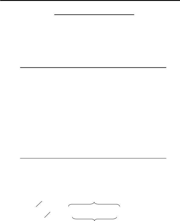
A new programmer-defined data type named MOTORTYPE has been created at the top of this listing. This data type is termed an enumerated data type because all possible values the data type can be given are listed in the type declaration. These values are named enumeration constants and are always of type int. Use mnemonic identifiers that are meaningful to improve readability of the program.
keyword enum Mnemonic identifiers
enum MOTORTYPE {UPFS, UPHS, BPFS, BPHS};
0 1 2 3
new data type name
These enumerated constants (integer values) are automatically assigned to the above identifiers.
Figure 8-23 Enumerated data types.

8 DRIVING MOTORS - DC & STEPPER 229
In the declaration shown in Figure 8-23, the new data type has the name MOTORTYPE. The enumerated constants 0, 1, 2, and 3 are automatically assigned to the mnemonic identifiers UPFS, UPHS, BPFS, and BPHS, respectively. We can declare a variable of this type as follows:
MOTORTYPE NewMotor;
Note that if you use a C compiler (Not a C++ compiler) then the equivalent declaration must be:
enum MOTORTYPE NewMotor;
NewMotor can take any value enumerated; i.e. the values listed between the two braces. Had we specified that the mnemonic UPFS was equal to say 2 as shown below, then UPHS, BPFS and BPHS would become 3, 4 and 5 respectively.
enum MOTORTYPE {UPFS = 2, UPHS, BPFS, BPHS};
Since all enumerated values are represented by integers, it is possible to carry out integer arithmetic on the data type. For example:
MOTORTYPE NewBreed;
NewBreed = UPFS + BPFS; //valid but meaningless!
While this is possible, it has no meaning whatsoever for our purposes. However, under certain circumstances integer arithmetic with enumerated types can be of benefit when used with care.
Referring to Table 8-10, the enumerated data type shown in Listing 8-8 can represent any of the stepper motor types we aim to control using our interface board. We can now return to study the StepperMotor class definition in Listing 8-8. It has four private data members described as follows.
MOTORTYPE MotorType
The first member data is MotorType. Once initialised this data member will store the type of stepper motor to be controlled.
unsigned char Switching[8]
This statement declares an array named Switching that has eight unsigned char elements. The program will load this array with the unique switching patterns for the type of stepper motor the user selects. These switching patterns are specified ahead when the functions for the class are defined.
int CycleIndex
The member data CycleIndex will be used as a subscript to scan through the array Switching and select the values of each of its single byte elements in the proper sequence to step-wise drive a stepper motor. To drive a stepping motor forward using full-steps, CycleIndex will have values 0, 1, 2, 3, 0, etc. To drive the same motor in reverse direction CycleIndex will have values 0, 3, 2, 1, 0, etc. Similarly, to drive a stepping motor forward using half-steps, CycleIndex
230 8 DRIVING MOTORS - DC & STEPPER
will have values 0, 1, 2, 3, 4, 5, 6, 7, 0, etc. When driving a stepping motor in reverse using half-steps, CycleIndex will have the values 0, 7, 6, 5, 4, 3, 2, 1, 0, etc.
int MaxIndex
This data member will be used to detect the position in the array Switching when a new cycle must recommence. As such MaxIndex stores the maximum value CycleIndex takes. For full-step control, only four elements of the Switching array are used, so the value of MaxIndex will be 4. However, all eight elements of the array Switching must be used for half-step control. In this case the value of MaxIndex will be 8.
The member function definitions of the StepperMotor class are given in Listing 8-9.
Listing 8-9 Member functions of the StepperMotor class.
StepperMotor::StepperMotor(MOTORTYPE motortype,
int baseaddress): Motor(baseaddress)
{
MotorType = motortype; CycleIndex = 0;
switch(MotorType)
{
case UPFS: MaxIndex = 4; Switching[0] = 0x11; Switching[1] = 0x12; Switching[2] = 0x22; Switching[3] = 0x21; break;
case UPHS: MaxIndex = 8; Switching[0] = 0x01; Switching[1] = 0x11; Switching[2] = 0x10; Switching[3] = 0x12; Switching[4] = 0x02; Switching[5] = 0x22; Switching[6] = 0x20; Switching[7] = 0x21; break;
case BPFS: MaxIndex = 4; Switching[0] = 0x99; Switching[1] = 0x69; Switching[2] = 0x66;

8 DRIVING MOTORS - DC & STEPPER 231
Switching[3] = 0x96; break;
case BPHS: MaxIndex = 8; Switching[0] = 0x99; Switching[1] = 0x09; Switching[2] = 0x69; Switching[3] = 0x60; Switching[4] = 0x66; Switching[5] = 0x06; Switching[6] = 0x96; Switching[7] = 0x90;
}
}
void StepperMotor::Forward()
{
if(++CycleIndex == MaxIndex) CycleIndex = 0; WritePort0(Switching[CycleIndex]); delay(259-GetSpeed());
}
void StepperMotor::Reverse()
{
if(--CycleIndex == -1) CycleIndex = MaxIndex -1; WritePort0(Switching[CycleIndex]); delay(259-GetSpeed());
}
void StepperMotor::Brake()
{
switch(MotorType)
{
case UPFS: case UPHS: WritePort0(0x11); break;
case BPFS: case BPHS: WritePort0(0x99);
}
}
As usual, the constructor initialises the private data members of the class. If a motor type is specified in the actual argument for the parameter motortype, it will be assigned to the private data member MotorType. The CycleIndex is always initialised to 0. The MaxIndex is either set to 4 or to 8 depending on full-
232 8 DRIVING MOTORS - DC & STEPPER
step control or half-step control. The array Switching is initialised depending on the motor type and the operating mode, explained as follows.
The MotorType is tested in a switch statement which is used to fill the array Switching with appropriate values for that combination of stepper motor and drive mode depending on the case value. The values that are written into the array Switching control the sequential switching of the H-bridges to drive a given stepper motor through its sequence of steps. Note that the stepper motors will use both H-bridges and have almost full supply voltage applied to their respective windings during each step. Their speed/position is controlled by the rate/number of steps. As such they do not use pulse width modulation for speed or torque control.
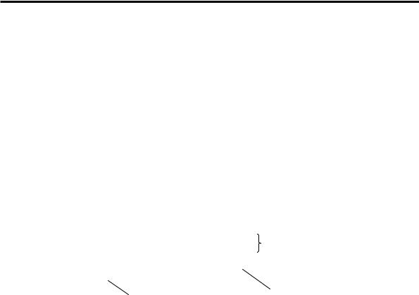
The Forward() function of the StepperMotor class operates in a similar manner as the Reverse() function, and so only the Forward() function is explained (see Figure 8-24).
void StepperMotor::Forward() |
|
|
{ |
|
|
if(++CycleIndex == MaxIndex) |
CycleIndex is incremented |
|
CycleIndex = 0; |
and tested for exceeding its limit. |
|
If exceeded it will be reset. |
||
WritePort0(Switching[CycleIndex]); |
delay(257-GetSpeed());
}
Contents of the array Switching
Speed is controlled by inserting a controlled delay between consecutive writes to the port.
are written to the port, one element per step delay.
Figure 8-24 Operation of the Forward() function.
The Brake() function implements a switch statement to apply braking appropriate to the motor type; a unipolar stepper motor or a bipolar stepper motor. Dynamic braking is applied uniquely for two of the four cases by closing and opening the required switches of the H-bridge. Note that in the configuration we have used for unipolar stepper motors, the armature cannot be short-circuited. Instead, voltage is not applied to the armature windings.
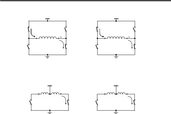
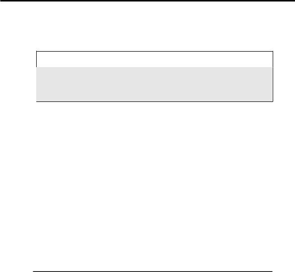
The H-bridge connections for Bipolar and Unipolar Stepper Motors are shown in Figure 8-25 and Figure 8-26 respectively. All the classes have been defined and the definitions of all member functions have been provided. The implementation of the class hierarchy is now complete. We now need to develop a main() function to make use of these classes.
8 DRIVING MOTORS - DC & STEPPER 233
Vm1 Vm2
A |
|
H-bridge 1 |
B |
|
|
H-bridge 2 |
|
|
|
A |
|
|
B |
||
(D0) |
I M1 |
M2 |
(D1) |
(D4) |
I M1 |
M2 |
(D5) |
+ |
|
|
+ |
|
Coil (Phase) 1 |
I |
D |
Coil (Phase) 2 |
I |
C |
|
C |
D |
|
(D2) |
|
(D3) |
(D6) |
(D7) |
Figure 8-25 H-bridge connections for a Bipolar Stepper Motor.
Vm1 Vm2
|
M1 |
+ |
M2 |
|
M1 |
+ |
M2 |
|
|
_ |
|
|
_ |
||
|
|
Coil (Phase) 1 |
I |
|
|
Coil (Phase) 2 |
I |
C |
|
|
C |
|
|
||
|
Lower half of |
D |
|
Lower half of |
D |
||
(D0) |
|
(D1) |
(D4) |
|
(D5) |
||
|
|
H-bridge 1 |
|
|
|
H-bridge 2 |
|
Figure 8-26 H-bridge connections for a Unipolar Stepper Motor.
8.6 Virtual Functions - Application
We are now ready to develop an application that makes use of virtual functions. This application will enable any of the types of motor accommodated in our class hierarchy developed earlier to be driven:
1.DC motors.
2.Unipolar stepper motors with dual-phase full-step control.
3.Unipolar stepper motors with half-step control.
4.Bipolar stepper motors with dual-phase full-step control.
5.Bipolar stepper motors with half-step control.
We will initially develop that part of the application that controls a ‘motor’ using the mechanism of virtual functions. Then we will add code to the program that allows a user to select a motor type to be driven.
The principal advantage of using virtual functions is the ability to write programs that can automatically bind a function to its associated object type at run-time. This allows us to write a very generic program. We start writing such a program by selecting a variable that can represent any of the objects in the hierarchy. The ideal
234 8 DRIVING MOTORS - DC & STEPPER
variable will be associated with the Motor class; the base class for all the real motor classes in the hierarchy. A pointer (which is a variable) to this class can point to any of the objects of its derived classes as explained below.
C++ |
Base Class Pointers |
|
|
A base class pointer can point to objects of its class or it can point to any objects
of its derived classes. When we use a base class pointer to point to an object
from a derived class and a virtual function is called through this pointer, the
corresponding member function of that derived class will be selected and called.
Therefore, we can create a pointer to the Motor class as shown below and use it to point to any of the real motor classes derived from it:
Motor *MotorPtr;
Our particular program will carry out the following steps:
1.Drive the motor forward at a speed of 150 until a key is pressed.
2.Drive the motor forward at a speed of 255 until a key is pressed.
3.Reverse the motor at a speed of 150 until a key is pressed.
4.Reverse the motor at a speed of 255 until a key is pressed.
5.Stop the motor (braking).
6.Turn off power to the motor.
The code that implements these requirements is shown in Listing 8-10. Here we use the function kbhit() to detect a key press and the function getch() to clear the keyboard buffer after the key press.
Listing 8-10 Generic code to control 'a Motor'.
Motor *MotorPtr;
// Insert statements to choose a specific motor here
//..... Motor control part starts here .....
MotorPtr->SetSpeed(150); while(!kbhit()) MotorPtr->Forward(); getch(); // clear keyboard buffer
MotorPtr->SetSpeed(255); while(!kbhit()) MotorPtr->Forward(); getch();
MotorPtr->SetSpeed(150);