

Interfacing with C plus plus-programing communication with microcontrolers (K. Bentley, 2006)
.pdf8 DRIVING MOTORS - DC & STEPPER 205
Bipolar Motor
This type of motor uses coil currents that reverse in direction throughout the stepping sequence, as shown in the preceding text. To achieve this reversal of current, bipolar voltages are applied to the coil windings. A bipolar power source with +ve, –ve and ground potentials can be used with four switching transistors to drive this type of motor. However, the usual means of implementing this form of drive is to use a single polarity power supply with eight switching transistors, configured using two separate H-bridge circuits as shown in Figure 8-7. Bipolar type motors are easily recognized since they have only four connection leads.
|
+V |
|
|
|
+V |
|
SW1 |
|
SW2 |
SW1 |
|
|
SW2 |
I A1 |
Coil 1 |
A2_ |
|
I B1 |
Coil 2 |
B2_ |
+ |
|
|
|
+ |
|
|
SW3 |
|
I |
SW3 |
|
|
I |
|
SW4 |
|
|
SW4 |
Figure 8-7 Bipolar drive using two H-bridge circuits.
Unipolar Motor
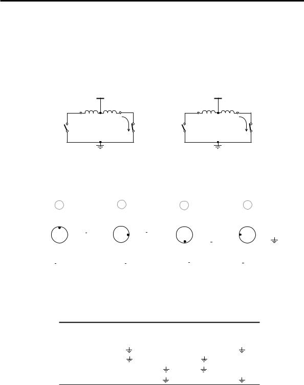
This type of motor uses coil winding currents which flow in one direction only. In order to obtain a reversal of magnetic field at each stator tooth, the coil is wound in two halves as shown in Figure 8-8. One half of the coil is wound clockwise around the stator tooth and the other half of the coil is wound anticlockwise around the stator tooth – known as a bifilar winding.
+ Volts
N
|
|
S |
A1 |
Wound |
Wound |
+ Volts |
S |
|
N |
Clockwise |
Anticlockwise |
N |
|
A2 |
|
|
|
|
|
S |
|
|
Bifilar Coil |
|
|
|
|
|
|
|
B2 |
B1 |
|
|
|
Figure 8-8 Unipolar motor – bifilar coil.
206 8 DRIVING MOTORS - DC & STEPPER
The wire connection halfway through the coil is connected to the positive power supply. Only one half of the coil is energised at a time. A north pole is produced when one half of the coil is energised by connecting its end to ground potential; a south pole is produced by energising just the other half of the coil by grounding its end. This is shown in Figure 8-9, Figure 8-10 and Table 8-3. Note that a north pole is produced when coil winding A1 or B1 are grounded; conversely grounding A2 or B2 results in a south pole.
+V +V
A1 |
+ |
A2_ |
|
B1 |
+ |
B2_ |
|
Coil 1 |
I |
|
|
Coil 2 |
I |
SW1 |
|
SW2 |
SW3 |
|
||
|
|
|
SW4 |
Figure 8-9 Unipolar coil drive.
|
1 |
|
|
|
|
|
|
2 |
|
|
|
|
|
|
|
|
|
|
3 |
|
|
|
|
|
4 |
|
|||||||||||||
|
|
|
N |
|
|
|
|
|
|
S |
|
|
|
|
|
|
S |
|
|
|
|
|
|
|
|
|
N |
|
|||||||||||
S |
|
|
|
S |
A1 |
|
|
|
|
S |
N |
A1 |
|
|
|
|
N |
|
N |
A1 |
|
|
|
|
|
|
S |
A1 |
|||||||||||
|
|
|
|
|
|
|
|
|
|
|
|
|
|
|
|
|
|
||||||||||||||||||||||
|
|
|
|
|
|
|
|
|
|
|
|||||||||||||||||||||||||||||
|
N |
N A2 |
|
|
|
|
|
|
S |
N A2 |
|
|
|
|
S |
S A2 |
|
|
|
|
N |
S A2 |
|||||||||||||||||
|
|
|
|
|
|
|
|
|
|
|
|
|
|
|
|
|
|
|
|
|
|
|
N |
||||||||||||||||
|
|
|
|
|
|
|
|
|
|
|
|
|
|
|
|
|
|
|
|
|
|
|
|||||||||||||||||
|
|
|
|
S |
|
|
|
|
|
|
N |
|
|
|
|
|
|
N |
|
|
|
|
|
|
|
|
|
|
S |
|
|||||||||
|
B2 B1 |
|
|
|
|
|
|
B2 B1 |
|
|
|
|
|
|
B2 B1 |
|
|
|
|
|
|
B2 B1 |
|
||||||||||||||||
|
|
|
|
|
|
|
|
|
|
|
|
|
|
|
|
|
|
|
|
|
|
|
|
|
|
|
|
|
|
|
|
|
|
|
|
|
|
|
|
Figure 8-10 Full-stepping sequence – unipolar motor.
Table 8-3 Full-stepping sequence for unipolar motor.
Coil Contact Voltage
Step Position |
A1 |
A2 |
B1 |
B2 |
1
2
3
4
8 DRIVING MOTORS - DC & STEPPER 207
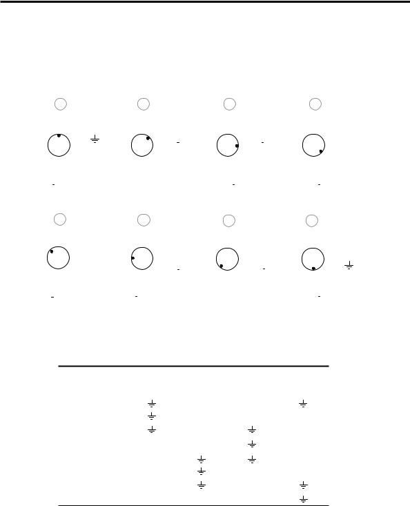
Half-stepping is achieved by energising two half coils together followed by energising only one coil in a repetitive sequence, generating a similar sequence of magnetic fields when half-stepping a bipolar motor. Figure 8-11 and Table 8-4 show the half-stepping sequence for a unipolar motor.
|
1 |
|
2 |
|
|
|
|
|
|
3 |
|
|
|
4 |
|
|
|
|||||||
|
|
|
N |
|
|
|
|
|
|
|
|
S |
|
|
|
S |
|
|||||||
S |
|
|
|
S |
N |
A1 |
A1 |
|
|
|
|
S |
N |
A1 |
|
|
N |
A1 |
||||||
|
|
|
|
|
|
|
|
|
||||||||||||||||
|
|
|
|
|
|
|
|
|
||||||||||||||||
|
N |
S N S N |
|
|
|
|
|
|
S |
N |
|
|
|
|
|
|
|
|||||||
|
|
|
A2 |
A2 |
|
|
|
|
|
|
A2 |
|
|
S |
A2 |
|||||||||
|
|
|
|
S |
|
|
|
|
|
|
|
|
N |
|
|
|
N |
|
||||||
|
B2 B1 |
|
B2 B1 |
|
|
|
|
|
|
B2 B1 |
|
|
|
B2 B1 |
|
|||||||||
|
|
|
|
|
|
|
|
|
|
|
|
|
|
|
|
|
|
|
|
|
|
|
|
|
8 |
|
7 |
|
|
|
|
|
|
|
|
6 |
|
|
|
|
5 |
|
|
|
||||||
|
|
|
N |
|
|
|
N |
|
|
|
|
|
|
|
|
|
|
|
|
|
S |
|
|||
|
|
|
S |
A1 |
|
S |
|
A1 |
|
|
|
|
|
S |
|
A1 |
|
|
N |
|
N |
A1 |
|||
|
|
|
|
|
N |
S |
|
|
|
|
|
N |
N |
S |
|
|
|
|
|
S A2 |
|||||
|
|
N |
A2 |
|
|
|
N |
A2 |
|
|
|
|
|
A2 |
|
|
|
S |
|||||||
|
|
|
|
|
|
|
|
|
|
|
|
|
|
|
|
|
|
|
|
||||||
|
|
S |
|
|
|
|
S |
|
|
|
|
|
|
|
|
|
|
|
|
|
N |
|
|||
B2 B1 |
|
|
B2 B1 |
|
|
|
|
|
|
|
B2 B1 |
|
|
|
|
B2 B1 |
|
||||||||
|
|
|
|
|
|
|
|
|
|
|
|
|
|
|
|
|
|
|
|
|
|
|
|
|
|
Figure 8-11 Half-stepping sequence – unipolar motor.
Table 8-4 Half-stepping sequence for unipolar motor.
Coil Contact Voltage
Step Position |
A1 |
A2 |
B1 |
B2 |
1
2
3
4
5
6
7
8
For a unipolar motor to have the same number of turns per winding as a bipolar motor, the wire diameter must be decreased due to its bifilar winding scheme. This
208 8 DRIVING MOTORS - DC & STEPPER
reduction in wire diameter leads to an increase in coil resistance and lowers the motor torque by approximately 30% at low step rates. At higher step rates, unipolar motor performance exceeds that of bipolar wound motors.
Stepper motors come in a variety of wire configurations as shown in Table 8-5. The five-wire unipolar motor is identical to the six-wire unipolar motor except the two power supply wires are connected together internally and only one wire is brought outside the motor case.
Table 8-5 Stepper motor wire configuration.
Wire |
|
Arrangement |
Motor Type |
|
|
4-wire |
Bipolar – 2 phase |
4-wire |
Variable Reluctance – 3 phase |
5-wire |
Unipolar – 2 phase |
6-wire |
Unipolar – 2 phase |
8-wire |
Bipolar – 4 phase |
The eight-wire bipolar motor has two pairs of two phases (independently wound coils). This arrangement allows a pair of phases to be connected in series or in parallel. A series-connected configuration effectively doubles the amp-turns producing twice the torque at lower speeds. The inductance of the effective coil is proportional to the number of turns squared, meaning that the inductance is now raised four-fold. Winding resistance is now double, which lowers the maximum value of current through the winding in order to not exceed the motor power rating.
Connecting the eight-wire motor in a parallel configuration does not change the effective number of turns and therefore does not increase the winding inductance. The effective winding resistance is now halved, meaning that the motor can be driven at higher levels of winding current for the same power dissipation. This will give improved torque at this higher current.
A series-connected configuration of phases leads to a rapid drop in torque as speed increases. This occurs because the time constant of the winding, being equal to inductance divided by resistance, is now twice that of a single connected phase. The parallel-connected windings perform much better at high speed than the series configuration since their winding time constant is half that of a single winding and therefore ¼ that of the series configuration. Additionally, the torque curve is flatter for a motor connected in parallel, producing greater shaft power.
8.3.3 Stepper Motor Control
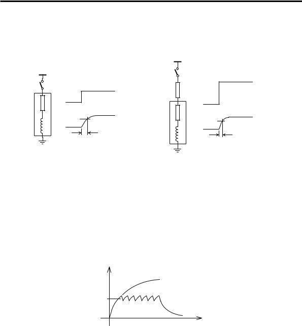
Stepper motor performance is compromised when driven by a simple H-bridge circuit as shown previously in this chapter. The coil current requires finite time to increase in level once the controlling switch (transistor) is ‘closed’. Since the
8 DRIVING MOTORS - DC & STEPPER 209
winding has inductance (L) and resistance (R), the current (I) will increase exponentially with increasing time according to the value of the winding time constant (Ω) as shown in Figure 8-12.
winding
+V
V
R
I
63%
L
ΩL/R
+2V
|
2V |
|
|
|
R |
|
|
winding |
R |
I |
|
63% |
|||
|
|||
|
|
L
Ω L/2R
Figure 8-12 Regular drive and Series resistance drive.
One means of reducing this winding time constant is by using series resistance drive. In this scheme, an external resistor is added in series to the winding circuit. If this resistor was say equal in value to the resistance of the wound coil and the applied voltage doubled, the peak current (I) through the winding would remain the same, but the winding time constant is now halved. Although this form of motor control increases the high-speed torque, it is inefficient due to the loss of power generated by the current flowing through the added external resistor.
Current
I
Time
Figure 8-13 Coil winding current under chopper drive.
A better approach to stepper motor control is known as chopper drive. The voltage applied to the winding is raised similar to that for the series resistance drive scheme but an added resistor is not used. This improves the rise-time of the current through the winding. Without using an added resistor, the current would eventually increase and exceed the motor’s rated winding current if some form of voltage control was not used. To prevent this excessive current build-up, a current sense resistor (with

210 8 DRIVING MOTORS - DC & STEPPER
small resistance) is used to measure the winding current. When the level of rising current reaches the rated value of the winding, the applied voltage to the motor control circuit is turned off, preventing any further current rise. Naturally, the winding current will now decay while the winding is not being powered. The sense resistor is used to monitor this decay so that voltage can be re-applied to the motor control circuit when the level of current has dropped a small amount below the rated value. This cycle of current build-up and decay continues until it is time to turn off the winding current for the next step sequence as shown in Figure 8-13.
There is a more refined technique used to drive stepper motors known as microstepping. This drive scheme proportions the level of individual coil winding current to produce intermediate stepping positions within a normal full-step. Accurate control of coil current is needed and high-resolution microstepping in excess of several thousand steps per revolution is possible.
Motor controllers that use integrated circuits are available to simplify the task of stepper motor control. These circuits contain waveform-generating logic, power transistor switches, and associated protection diodes to control the damaging effect of back-emf (electromagnetic force) produced when coil currents are switched off.
8.3.4 Stepper Motor Specification
Several terms such as holding torque, dynamic torque, pull-in torque, pull-out torque, and ramped step rate are used to specify stepper motor performance. These terms are briefly explained in Table 8-6.
|
Table 8-6 Stepper motor terminology. |
Holding torque |
That torque which the motor generates when stationary. |
Dynamic torque |
The torque generated by the motor when rotating. This torque |
|
drops as motor speed increases due to the effect of the motor’s |
|
time constant and the reduced time to build-up current. |
Pull-in torque (start without error torque)
The pull-in torque is the maximum torque available to be applied to the motor load when starting from rest for a particular step rate (or when coming to a stop without losing steps). It does not include that portion of motor torque needed to accelerate the inertia of the motor itself.
Pull-out torque |
The maximum torque that can be applied to the motor load |
(running torque) |
during steady speed without losing steps. This torque is higher |
|
than the pull-in torque because the motor is not being |
|
accelerated and therefore no torque is consumed for this |
|
purpose. |
Ramped step rate |
This is the step rate which avoids any loss of steps during |
|
periods of acceleration or deceleration. |

8 DRIVING MOTORS - DC & STEPPER 211
So far in this chapter we have discussed the principles of operation of DC motors and stepper motors. Let us now turn our attention to writing object-oriented programs to drive these motors using the motor drive circuits of the interface board. In the coming sections we will encounter the most powerful feature of object-oriented programming – virtual functions.
The approach taken in the following sections is to first develop a class hierarchy to represent DC motors and all forms of stepper motors discussed earlier in this chapter. Then we will use the classes in this hierarchy to develop a generic program that will drive any type of motor in the hierarchy.
8.4 A Class Hierarchy for Motors
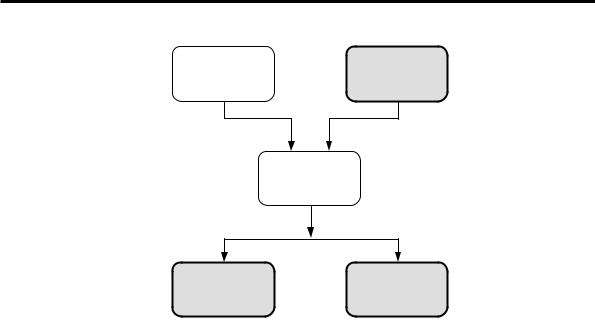
All the motors to be included in our class hierarchy will be driven using the interface board. Therefore, while the class hierarchy is in principle for motors, interfacing also plays an important role. We can identify two major categories for all motors described in this chapter. They are; i) DC motors and ii) Stepper Motors. Stepper motors fall into two types; Unipolar Stepper Motors and Bipolar Stepper Motors. These two types of stepper motors can be controlled in two different ways; full-step control and half-step control. DC motors have not been further subdivided.
To start with, we can think of motors ‘in general’ as abstract objects. A ‘motor’ will remain an abstract concept until we can describe all its relevant details. Therefore, a good starting point for our class hierarchy is an abstract motor class that encompasses the most common features of all motors in the hierarchy. Interfacing these motors to the interface board is also a very basic requirement for all the motors. In our case, all motors will be controlled via the parallel port and so the ParallelPort object we developed earlier can be used for this purpose. Since interfacing is necessary for all motors of the hierarchy, the ParallelPort class must join the hierarchy at a very early stage. The proposed class hierarchy is shown in Figure 8-14.
At the root of the class hierarchy is the abstract class AbstractMotor that represents all motors. The ParallelPort class is also at the same level as the AbstractMotor class. However, the ParallelPort class developed earlier is not an abstract class. It is a real class since objects can be instantiated from it.
The Motor class is derived by multiple inheritance from the two base classes
AbstractMotor and ParallelPort. The Motor class is also an abstract class since it is not yet a fully described object class of the motor hierarchy. This means the class lacks the finer details of the specific motor types needed to complete the member function definitions. However, the objects of the Motor class have more capabilities than the objects of the AbstractMotor class, namely they can communicate with devices via the parallel port.
212 8 DRIVING MOTORS - DC & STEPPER
AbstractMotor |
ParallelPort |
(Abstract class) |
(Real class) |
Motor with Interface (Abstract class)
DCMotor |
StepperMotor |
(Real class) |
(Real class) |
Figure 8-14 Motor class hierarchy.
The Motor class is then used to derive the two classes DCMotor and
StepperMotor. At this level DCMotor and StepperMotor are completely described and must be real classes. The class hierarchy ends here.
The question arises; why not derive further classes to represent, for example, dualphase bipolar stepper motors in half-step control? The answer is as follows. The functional characteristics of a dual-phase bipolar stepper motor in half-step control are different from a dual-phase unipolar stepper motor in full-step control. However, from a software point of view, this is analogous to two cars having different colour. The different motor drive schemes are certainly not analogous to a normal car and a luxury car. When two different coloured cars are needed, the choice of colour can be handled by changing the value of a parameter. A new class is not necessary for each colour. Our approach in treating different kinds of stepper motors will be along similar lines.
8.5 Virtual Functions – An Introduction
A virtual function is a function that has the same function signature throughout a class hierarchy although behaves according to its definition in each class. Virtual functions are polymorphic in nature but with a subtle difference. As discussed in Chapter 4, polymorphic functions are functions throughout a class hierarchy with the same name, the same number of parameters, same sequence of parameters and same types of parameters. However, their bodies are programmed differently to suit the requirements of each class. Virtual functions have all the features of polymorphic functions, except the keyword virtual is added right at the front of

8 DRIVING MOTORS - DC & STEPPER 213
function declarations within their classes. Although virtual and non-virtual functions appear to be quite similar, there are significant advantages when using virtual functions. They allow the implementation of a very powerful feature known as late binding which will be explained in more detail later in this chapter.
The benefits of late binding are strictly linked to virtual functions within a class hierarchy. Virtual functions are added at first to a base class and then later implemented throughout the derived classes of the hierarchy. This arrangement provides the primary link needed between a virtual function of the base class and a virtual function of a derived class somewhere down the class hierarchy. Any virtual functions of any derived class can be called using a pointer to the base class. Despite using a base-class pointer, rather than a pointer to the derived class itself, at run-time the base-class pointer will select the correct function from the derived class, thanks to the mechanism that links virtual function within a class hierarchy.
If virtual functions are not used to select the correct function to match the object chosen by the user at run-time, the developer needs to provide additional code to carry out these tasks. This extra code will include all the necessary program statements placed within a framework of “if-then-else“ logic or switch statements. When class hierarchies are large and complex, this extra programming can be an immense burden and produce programs that are difficult to debug and maintain. If a new class is added to the hierarchy, the entire program needs to be modified. As can be imagined, this is not a very efficient approach to programming.
Virtual functions and associated late binding alleviates the program developer from needing to generate this extra code. The developer writes a generic program using virtual functions. The compiler and linker are now managing this task. As a result, programming and debugging times are markedly reduced. Furthermore, minimal change to code is required to incorporate a new addition to the class hierarchy. These advantages will become evident as we work through the example programs ahead.
AbstractMotor Class
As mentioned previously, the principal motive underlying the development of the AbstractMotor class as a base class is to form a foundation for the network of virtual functions. All classes derived from the AbstractMotor class will inherit all its functions. Only some of the functions can be completely defined at this early stage, while the remaining functions will be skeletal due to a lack of exact details for the ‘motors’ involved. A thoughtful selection of data and functions to be included in a base class for motors is as follows:
1.A data member to store the set speed of the motor.
2.A mechanism for functions outside the class to obtain the set speed.
3.A function to drive ‘a motor’ forward.
4.A function to drive ‘a motor’ in reverse.
5.A function to brake ‘a motor’.
6.A function to turn ‘a motor’ off (no applied power).
214 8 DRIVING MOTORS - DC & STEPPER
A class definition for the AbstractMotor class is given in Listing 8-1.
Listing 8-1 AbstractMotor class.
class AbstractMotor
{
private:
int Speed;
public:
AbstractMotor();
void SetSpeed(int speed); int GetSpeed();
virtual void Off()=0; virtual void Forward()=0; virtual void Reverse()=0; virtual void Brake()=0;
};
We haven’t seen the bold font code shown in Listing 8-1. It will be discussed in the sections ahead.
The AbstractMotor class has Speed as a private data member, which is of type int. The member function SetSpeed() receives speed as a parameter and then sets the value of data member Speed to equal speed. The public member function GetSpeed() can be called by any function in the program to obtain the value of private data member Speed. The Off() function turns off all power to the motor. The function Forward() is used to drive the motor forward at the speed specified in Speed. Similarly, the function Reverse() is used to drive the motor in reverse direction at the speed specified by Speed. The Brake() function can be used to short-circuit the motor windings to stop the motor rotation, in the minimum time.
We will now provide the definitions for all member functions of the AbstractMotor class. The AbstractMotor class does not drive specific types of motors. Rather it provides general functions that will be overridden in its derived classes to suit specific types of motor. Without knowing the exact details of the motor, we cannot define the functions Off(), Forward(), Reverse() and Brake(). If we cannot define the functions, why did we include them as member functions? One reason is that it is good to specify the form of the objects of the hierarchy at its start to maintain a high level of conformity throughout the hierarchy. This helps us write code that maintains the relationships with objects of the entire hierarchy. For example, all classes of the hierarchy will have a function named Forward(). The subsequent derived classes will then redefine the inherited Forward() function to apply specifically to their respective class. The other reason is associated with virtual functions and late binding.