

Interfacing with C plus plus-programing communication with microcontrolers (K. Bentley, 2006)
.pdf114 6 DIGITAL-TO-ANALOG CONVERSION
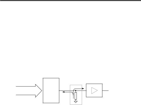
zero volts (the negative side in this particular case) is termed a unipolar output. The other type of DAC output is one that which crosses between the positive and negative sides of zero volts, and is termed a bipolar output. Figure 6-9 shows the resistor configuration needed by the current-to-voltage converter for it to operate in a bipolar mode.
Digital8 Inputs |
CurrentOutput (sinking) |
|
+5V |
|
|
Voltage |
|
||
|
|
i |
R |
|
8-bit Logic |
|
|
VDAC |
Vout |
(8 lines) |
|
|
|
|
|
|
Current to |
|
|
|
|
|
|
|
|
|
|
Converter |
Voltage Buffer |
|
|
|
& Inverter |
|
DAC0800 |
|
|
||
|
|
|
||
Figure 6-9 Bipolar current-to-voltage conversion.
The output voltage (VDAC) of the bipolar current-to-voltage converter is evaluted from the relationship:
VDAC = +5V – Voltage drop across R
=+5V – i x R
The minus sign in the preceding equation comes from the fact that the current i flows into the DAC0800, and that current flows from a more positive voltage to a less positive voltage – therefore the voltage at the current-to-voltage converter will be equal to +5V minus the voltage drop across resistor R.
As current draw i into the DAC output increases, the voltage at the DAC output drops from +5V (all 8 logic inputs zero) to lower voltages, passing through zero volts and into the negative voltage region, eventually reaching –5V (all logic inputs high, and using the appropriate value for resistor R). The current-to-voltage converter on the interface board can be configured in unipolar or bipolar mode by fitting a link in either of two positions respectively.
Table 6-1 Current-to-Voltage Converter Output.
DAC Logic Input |
Unipolar mode |
Bipolar mode |
255 |
-5V |
-5V |
0 |
0V |
+5V |
|
|
|
Table 6-1 summarises the output voltage of the current-to-voltage converter for both unipolar and bipolar configurations of the resistor R (chosen to have the appropriate value).
6 DIGITAL-TO-ANALOG CONVERSION 115
Usually, we expect the output voltage from a DAC to be lowest when all logic input bits are zero and highest when all logic input bits are high (255 for an 8-bit DAC). To meet this convention, the current-to-voltage converter output needs to be inverted to produce +5V for all logic input bits high and 0V for all logic input bits low when in unipolar mode. Bipolar mode should produce +5V when all logic input bits are high and –5V for all logic input bits at zero. The Buffer and Inverter circuit block shown ahead in Figure 6-11 and Figure 6-12 perform this voltage inversion.
A typical inverter circuit will need to draw some current iχ through its input as shown in Figure 6-10. If this current draw is significant, it will adversely affect the voltage generated across R. This occurs because we now have two currents i and iχ
flowing through R with iχ generating an error voltage VERROR = iχ x R. The total voltage across resistor R is V = (i + iχ) x R, equal to the correct voltage (i x R),
plus VERROR.
Digital8 Inputs |
CurrentOutput |
(sinking) |
|
iχ |
8-bit Logic |
|
|
|
Vout |
(8 lines) |
|
|
i |
|
|
|
|
R |
|
|
|
|
|
|
|
|
|
|
Inverter Only |
DAC0800 |
|
Current to |
||
|
|
|
|
|
|
|
|
|
Voltage |
|
|
|
|
Converter |
Figure 6-10 Inverter circuit affecting voltage V.
To ensure that we do not draw a significant current into the inverter circuit, we precede it with a Voltage Buffer circuit. The Voltage Buffer draws a minute amount of current (~200 nA), not enough to interfere with the accuracy of the DAC current-to-voltage converter.
6.2.3.1 The Voltage Buffer Circuit
This circuit performs the function of buffering the output voltage of the DAC current-to-voltage converter as mentioned previously. The Buffer uses a special opamp configuration that draws almost zero current. This circuit is shown in Figure 6-11.
116 6 DIGITAL-TO-ANALOG CONVERSION
i = 0
i = 0 |
VBUFFER |
DAC0800 Output Voltage (from current-to-voltage converter)
Figure 6-11 Voltage Buffer circuit.
Remember that the current flowing into an op-amp input pin is effectively zero, therefore the current flowing from the DAC0800 current-to-voltage converter circuit and into the op-amp +ve input pin is zero. This op-amp is configured using
negative feedback. The output of the op-amp (VBUFFER) will be driven to ensure there is effectively zero voltage between its –ve and +ve input pins. Therefore, the
output voltage of the op-amp will follow or buffer the input voltage (from the DAC) present at its +ve input.
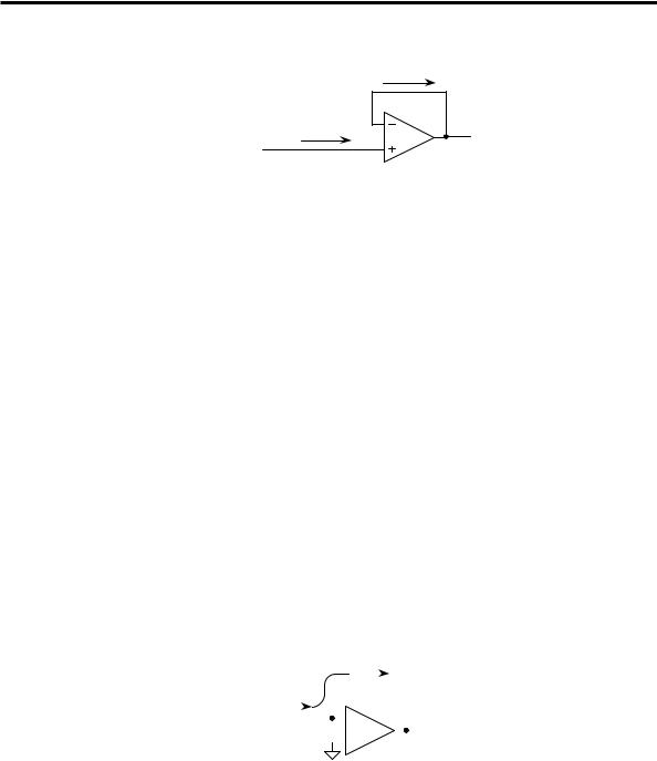
6.2.3.2 The Voltage Inverter Circuit
The DAC output circuitry produces a falling voltage as the input bit number value increases (see Table 6-1). The Voltage Inverter circuit inverts the voltage signal generated by the DAC current-to-voltage converter circuit, to give an increasing output voltage as the DAC input increases in value. We have already examined a circuit that produces an output voltage with opposite polarity to that presented to its input: the current-to-voltage op-amp circuit. That circuit performs voltage inversion and also amplification, where the amplification or gain is equal to the ratio of the resistor Rf to Ra. If we make Rf equal to Ra then we will have a gain of unity – now we have an inverter as shown in Figure 6-12. The circuit analysis of the inverter is identical to that carried out in Section 6.2.1.
|
|
|
|
|
|
|
|
|
|
|
|
|
i |
||||||
|
|
|
|
|
i |
|
|
|
|
|
|
|
|
|
|
|
|
|
|
|
|
|
|
|
|
|
|
|
|
Rf 10K |
|
|
|
|
|
||||
Vin |
|
|
|
|
|
|
|
|
|
|
|
|
|
|
|
|
|
Vout |
|
( - 1V ) |
Ra 10K |
|
|
|
|
|
|
|
|
|
|
|
|||||||
|
|
|
|
|
|
|
|
|
|
|
|||||||||
|
|
|
|
|
|
|
|
|
|
|
|
|
|
|
|
|
|
|
( +1V ) |
|
|
|
|
|
|
|
|
|
|
|
|
|
|
|
|
|
|
||
Figure 6-12 Op-amp Voltage Inverter circuit.
6 DIGITAL-TO-ANALOG CONVERSION 117
6.2.4 DAC Characteristics and Specifications
The DAC has some basic characteristics that specify its performance. These include settling time, non-linearity and full-scale error. The settling time is a measure of how fast the output of the DAC can change and settle to within half of a least significant bit (LSB - the smallest change in output voltage, caused by the 20 logic input). The DAC0800 has a typical settling time of 100 ns.
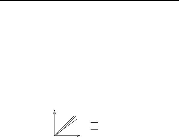
The linearity refers to the maximum deviation from the converter’s ideal input/output relationship – being the relationship between the DAC output value and the DAC input value, over the whole input range of the converter. Ideally, this relationship should be a straight line, the output increasing in value as the input increases. Figure 6-13 shows an ideal input/output relationship along with two independent errors, the offset error and the gain error.
The offset error is the voltage (or current) present at the output of the DAC when the digital input is zero. Ideally the offset error should be zero. Gain error occurs when the output of the DAC doesn’t increase by the correct amount for an increase in the digital input.
DAC
Output
(V or A) Ideal Input/Output Relationship Offset Error
Gain Error
Digital Input
Figure 6-13 DAC Input/Output Relationship.
The DAC0800 used in the interface board has the following relevant specifications. Its non-linearity is ρ0.1% over its rated temperature range (meaning that it has a linearity of 99.9%) and its full-scale error is ρ1 LSB (least significant bit), meaning that its maximum output value will be within ρ1 LSB of the true value corresponding to the ideal transfer function (input/output relationship).
6.3 Programming the Digital-to-Analog
Converter
At the end of the previous chapter, we developed an object class named ParallelPort. This object has the capability to input and output data using all three addresses of the PC’s parallel port. It can easily be used to drive an 8-bit Digital-to-Analog Converter. Only partial functionality of the ParallelPort

118 6 DIGITAL-TO-ANALOG CONVERSION
class is needed to drive the DAC on the interface board. The DAC just needs to receive an 8-bit number from the PC. This can be done by sending an 8-bit number from the PC to the interface board using the port at address BASE. This is an output port with eight parallel signals we can connect to the interface board. Since we already have ParallelPort as a completely packaged object class, we can use it to drive the DAC.
The rest of the chapter will progress as follows. First, we will develop a program using the ParallelPort object to drive the DAC. When this program is executed, the DAC system will generate an analog voltage proportional to the 8-bit number sent to it. We will then proceed to learn about inheritance using an exercise in which a new class is derived to represent the DAC. This new object may require extra functionality that is specific to the DAC. We will then turn our attention to restrictions imposed by various access attributes. The proper use of access attributes will be described in detail. We will proceed through several different versions of the same program, each time strengthening code reuse. The final program presented will then be used in future chapters as the most appropriate object-oriented program to drive the DAC.
The first program to drive the DAC is given in Listing 6-1. The class definition and the member function definitions of the ParallelPort object class are exactly the same as given in the previous chapter. In the main() function, an object is instantiated using the ParallelPort class and it is given the name D_to_A. Then the WritePort0() function of the object is used repeatedly to send different data to the parallel port each time. Following each WritePort0() function is a getch() function. These getch() functions force the program to wait for a key press before executing the next statement. This will allow you time to carry out measurements on the interface board to verify whether or not the correct analog voltage has been generated by the DAC system.
Table 6-2 Connections for the DAC.
BASE Address |
DAC0800 |
|
(Buffer IC, U13) |
(U8) |
|
|
|
|
D0 |
D0 (12) |
|
D1 |
D1 |
(11) |
D2 |
D2 |
(10) |
D3 |
D3 |
(9) |
D4 |
D4 |
(8) |
D5 |
D5 |
(7) |
D6 |
D6 |
(6) |
D7 |
D7 |
(5) |
Before running your DAC programs, configure the interface board as follows. Ensure that an operational 9V battery is connected to the terminal block (J14). Fit

6 DIGITAL-TO-ANALOG CONVERSION 119
the jumper on the interface board across the two-pin header position marked LINK1, to select unipolar mode (0V to +5V). When the connections are completed according to Table 6-2, the 8 bits of the port at address BASE of the parallel port will be connected to the 8-bit input of the DAC.
Listing 6-1 Digital-to-Analog Conversion using the ParallelPort object class.
/***************************************************** This program uses the ParallelPort object developed in the previous chapter to write a byte of data to the Digital to Analog Convertor (DAC). The DAC generates an analog voltage proportional to the value of the data byte it receives.
*****************************************************/
#include <iostream.h> #include <conio.h>
class ParallelPort
{
private:
unsigned int BaseAddress; unsigned char InDataPort1;
public:
ParallelPort(); // default constructor ParallelPort(int baseaddress); // constructor void WritePort0(unsigned char data);
void WritePort2(unsigned char data); unsigned char ReadPort1();
};
ParallelPort::ParallelPort()
{
BaseAddress = 0x378; InDataPort1 = 0;
}
ParallelPort::ParallelPort(int baseaddress)
{
BaseAddress = baseaddress; InDataPort1 = 0;
}
void ParallelPort::WritePort0(unsigned char data)
{
outportb(BaseAddress,data);

120 6 DIGITAL-TO-ANALOG CONVERSION
}
void ParallelPort::WritePort2(unsigned char data)
{
outportb(BaseAddress+2,data ^ 0x0B);
}
unsigned char ParallelPort::ReadPort1()
{
InDataPort1 = inportb(BaseAddress+1);
//Invert most significant bit to compensate
//for internal inversion by printer port hardware. InDataPort1 ^= 0x80;
//Filter to clear unused data bits D0, D1 and D2 to zero. InDataPort1 &= 0xF8;
return InDataPort1;
}
void main()
{
ParallelPort D_to_A;
cout << "Press a key ... " << endl; getch();
D_to_A.WritePort0(0);
cout << "Press a key ... " << endl; getch();
D_to_A.WritePort0(32);
cout << "Press a key ... " << endl; getch();
D_to_A.WritePort0(64);
cout << "Press a key ... " << endl; getch();
D_to_A.WritePort0(128);
cout << "Press a key ... " << endl; getch();
D_to_A.WritePort0(255);
}

6 DIGITAL-TO-ANALOG CONVERSION 121
The analog output voltage can be measured at the pin on the interface board labelled VDAC, which is connected to pin 7 of the operational amplifier LM358 (U10B). Each time you press a key, the program will output a slightly higher 8-bit value and the DAC will produce a corresponding higher analog voltage. Read the analog voltage by connecting a voltmeter between the pin marked VDAC on the interface board and a ground pin.
As described earlier, additional circuitry has been provided on the interface board to facilitate both unipolar and bipolar output from the DAC. Move the jumper to the position marked LINK2 on the interface board and re-execute the program to check the bipolar operation of the DAC system.
6.4 Derivation of Object Classes
In the last example, we used the ParallelPort object class to operate the DAC. This object is designed for general-purpose use of the parallel port. The ParallelPort object class is more than capable of handling the simple requirements of the DAC. However, using the ParallelPort object class for digital-to-analog conversion is not particularly appropriate. Instead, it is desirable to create an object class, which at least has a name that suits digital-to-analog conversion. This is an ideal situation to derive a class. We are for now merely applying a change in name which will reduce the complexity associated with the derivation of the new class. As we progress through the book we will confront more involved class derivations.
One of the main strengths of object-oriented programming is the re-useability of the program segments developed in the past. The C++ language has excellent mechanisms in place to expand the capabilities of an existing class and thereby to form a new super class. As described in Chapter 4, these super classes are known as derived classes. To be able to derive a class, a base class must exist. The derived classes are meant for more specific purposes than the base class. In our case, the general-purpose object class ParallelPort can be considered as the base class. The new class to be created needs to be more specific to suit the Digital-to-Analog Converter. Listing 6-2 shows the simplest way to create the new class.
Listing 6-2 Derivation of DAC class.
class ParallelPort
{
private:
unsigned int BaseAddress; unsigned char InDataPort1;
public:
ParallelPort();

122 6 DIGITAL-TO-ANALOG CONVERSION
ParallelPort(int baseaddress);
void WritePort0(unsigned char data); void WritePort2(unsigned char data); unsigned char ReadPort1();
};
class DAC : public ParallelPort
{
};
The class derivation is kept simple so that we can direct our attention to the principles of derivation of classes rather than the actual functionality of the DAC object class. The class definition for the ParallelPort object class is identical to that given in Chapter 5. The only new part in the above listing is the class definition for the object type DAC shown in bold typeface. The first line of the new object class definition is:
class DAC : public ParallelPort
Here, we derive a new class named DAC, using the existing class ParallelPort as the base class. The keyword public before ParallelPort, is referred to as an access specifier. We will return to access specifiers after considering the member data and member functions we inherited from the base class.
Inherited members of the DAC class
Here, the word inheritance is used to describe the fact that the derived class inherits all the member data and member functions of the base class. If you now take a closer look at the DAC object class, you will see that the body of the DAC class definition is empty. It was explained in Chapter 5 that if we do not provide our own constructor and destructor for the object class, the compiler will provide them. Therefore, although not visible, the DAC class has a default constructor and a default destructor provided by the compiler. Also, because the DAC class has been derived from the ParallelPort class, it has inherited all the members (both data and functions including constructors) of the ParallelPort class.
If we list the data members of the DAC class, they are as follows:
unsigned int BaseAddress; unsigned char InDataPort1;
The member functions of the DAC class are as follows:
DAC(); // Compiler-generated constructor (hidden). ParallelPort();
ParallelPort(int baseaddress);
void WritePort0(unsigned char data); void WritePort2(unsigned char data); unsigned char ReadPort1();

6 DIGITAL-TO-ANALOG CONVERSION 123
~ParallelPort(); // Inherited compiler-generated // destructor (hidden).
~DAC(); // Compiler-generated destructor (hidden).
NOTE
Note that we did not include destructors in the class definition for the
ParallelPort class and also in the class definition for the DAC class. Therefore,the compiler will generate a hidden default destructor for each of these classes as listed above. All compiler-generated constructors and destructors are
described as hidden to the programmer because they are invisible in the source
code. See Chapter 8 for a more detailed description of destructors.
The DAC class is equivalent to the ParallelPort class except that it has a default constructor and destructor provided by the compiler. It is clear that this particular class derivation is just a name changing exercise since we did not expand the capability of the DAC class. It can only do as much as the ParallelPort class and no more. However, if we need to enhance the power of the DAC class, it is an easy matter to add member data and member functions to the new DAC class in its class definition and then provide the definitions of the added functions.
Instantiating DAC objects (calling constructors)
The question to consider is “Can we use this class?” To instantiate an object of type DAC, we must call the constructor of the DAC class. It would be called in the declaration statement for the new object named D_to_A as shown below:
DAC D_to_A;
When the constructor of a derived class is first called, it will call the constructor of its inherited base class that takes whatever parameters it is being passed from the derived class constructor (this will be further explained ahead). The base class constructor instantiates its members and completes whatever tasks it has been coded to do. When it is finished it returns program execution back to the start of the body of the derived class constructor. The derived class constructor then instantiates its members and completes whatever tasks it has been coded to do.
In the case of this particular program, the DAC class does not have a programmergenerated constructor, so the compiler adds its own default constructor (takes no parameters). This is the constructor that is called when the above statement is executed. Before it performs its own tasks, it will call its inherited base class constructor. Because the derived class constructor is not passing an argument to the constructor of the base class, the constructor ParallelPort() and not the constructor ParallelPort(int baseaddress) will be called to allocate memory for the inherited base class members. If you look at the body of this constructor in Listing 6-1 you will see that it also initialises BaseAddress to the