

Interfacing with C plus plus-programing communication with microcontrolers (K. Bentley, 2006)
.pdf42 3 TESTING THE PARALLEL PORT
i
anode  cathode
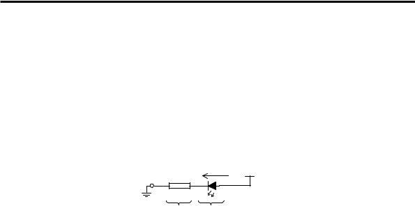
Figure 3-8 Conventional Current through a LED.
For current to flow in this direction, the anode must have a more positive voltage applied than the voltage at the cathode (known as forward voltage, VF). This difference in applied voltage (VF) typically needs to be approximately 2V for most LEDs and approximately 0.7V for ordinary diodes, if they are to conduct.
Current
(I)
IF
Normal Operating
Range of LEDs
VBR
-5V
VF (LED) |
Voltage |
2V |
(V) |
IR
Figure 3-9 Typical LED characteristic curve (without a series resistor).
A characteristic curve for a LED is shown in Figure 3-9. This curve shows the current through the LED and voltage across the LED for its normal range of operation, indicated by the bold portion of the curve at the right side of the current axis. When using the LED in its normal operating range, an increase in current through the LED will increase its light output. When the current exceeds the maximum limit for the LED (indicated by the value IF), the device will be destroyed. A current limiting resistor, shown in Figure 3-10, is used to control the current and prevent failure due to excessive current.
Note that if we reverse the voltage applied across the LED, we will reach the LEDs reverse breakdown voltage (VBR, shown as –5V in Figure 3-9). Once the reverse breakdown voltage has been exceeded, reverse current will increase to the point at which the device is destroyed (IR).
3 TESTING THE PARALLEL PORT 43
When we generate sufficient forward voltage to make the LED conduct, we say we have biased the device to operate. As mentioned previously, the LED will be destroyed if we do not use a resistor to limit the current flowing through it. The amount of current flowing through a resistor depends on the voltage across it. Since the LED and resistor are connected as shown in Figure 3-10, they share the same current. This circuit arrangement is known as a series circuit. Current through this circuit is analysed as follows.
If we know the voltage across the resistor we can work out the current flowing through it (and the LED) since Current = Voltage/Resistance.
i VCC (+5V)
Driver  330R
330R
Ground
(0V) 3V 2V
Figure 3-10 Current flow through the Series Circuit.
We know that the voltage across a conducting LED is approximately 2V and we also know that the total voltage across the series circuit from VCC to Ground is 5V. Therefore, the voltage across the resistor is:
5V – 2V = 3V
The current (I) through a resistor is given by voltage across the resistor, divided by its resistance in Ohms (:):
i.e. I = 3V / 330 : = 0.009 A (amperes are denoted by the symbol A.)
The currents flowing in electronic circuits are often small fractions of an ampere and so the units of milliamps (mA) which is 1/1000th of an amp are commonly used. Thus we have 0.009 amps which is 9 milliamps flowing through the LED and resistor.
Proceed to assemble and then test the hardware for the LED Driver circuit along with at least eight interconnecting leads, as explained in Appendix A.
3.4 Basic Output Using the Parallel Port
As described in Chapter 2, there are three addresses associated with the parallel port (typically being 0x378, 0x379 and 0x37A). Although we use the term parallel port, this ‘port’ is really three ports combined together. The simplest of the three ports is the one at address 0x378. In general, this port is only used for output, however, more recent computers have the capability to input data using this port

44 3 TESTING THE PARALLEL PORT
address. Nevertheless, to maintain compatibility, the software we have developed only uses data output to port 0x378. We will write a program that outputs a byte of data via port 0x378 to light up the respective LEDs on the interface board.
To verify the proper operation of our program, we need to connect the interface board to the parallel port of the PC. This is done using the interface board cable described in Chapter 2. The remainder of the connections to be carried out on the interface board must be made according to Table 3-1 below. Note that pin 1 of an IC on the interface board can be recognised by its rectangular shaped pcb pad. Make these connections using the interconnecting leads assembled earlier. When the connections are complete, the signal lines of the port at BASE address (0x378) will be connected to the Driver circuit that lights the eight LEDs via the Buffer IC on the interface board.
Table 3-1 Connections for basic output.
BASE Address |
ULN2803A Pin No. |
(Buffer IC, U13) |
(Driver IC, U3) |
D0 |
1 |
D1 |
2 |
D2 |
3 |
D3 |
4 |
D4 |
5 |
D5 |
6 |
D6 |
7 |
D7 |
8 |
|
|
The program shown in Listing 3-1 has several lines of program statements followed by comments. It uses a library function outportb() to output a byte of data to the port at BASE address. The port address and the data can be specified as actual arguments to outportb() at the time of calling. Since outportb() is a library function, we do not have to provide the body of the function. It comes from the library and will be searched for when linking takes place.
Listing 3-1 Writing to the port at Base address.
/***************************************************** WRITING TO A PORT (output operation)
This program outputs a certain bit pattern to the port at BASE address to light the respective LEDs on the interface board.
*****************************************************/

3 TESTING THE PARALLEL PORT 45
#include <dos.h>
#define BASE 0x378
void main()
{
outportb(BASE,255); // in binary, 255 = 1111 1111
//The number 255 can be changed to any value betwen 0
//and 255, causing the eight output signals to
//correspond to the binary value represented by the
//number. For example 65 = 0100 0001.
}
As mentioned in Section 1.2.2, the two lines starting with the hash sign (#) are compiler directives. The first compiler directive will include the header file dos.h (which is a source file). This file contains the prototype of the outportb() function. The header file dos.h also contains information about many other functions. However, as far as this program is concerned, only the information regarding the outportb()function is needed. The compiler would not be able to process the outportb() function, and the program could not use it if we did not include this header file. Note that the prototype does not specify how the function is to be executed. In other words, until linking takes place, the program will not have access to the actual instructions contained in the function.
The second compiler directive is a define statement. It simply instructs the preprocessor to replace any occurrences of BASE in the program by the hexadecimal number 0x378. Using the word BASE instead of 0x378 makes the code more readable since it is easier to relate to the word BASE than a number. In addition, if we ever wanted to change the base address, we only need to modify the define statement and the preprocessor will automatically implement that change in address throughout the program. The define statement can be used when writing larger programs to simplify the task of coding and improve readability.
Next we encounter the main() function (the only function in this particular program) where all C++ programs start their operation. Usually a typical C++ program will have many functions coded (defined). The keyword void indicates that the main() function will not return any value. The body of the main() function starts with the open brace ({) just after the line void main() followed by its instructions. The only executable statement in this program is outportb(BASE,255). This statement is used to output a byte of data from the PC. After a few comments, the body of the main function ends with a close brace (}).
The function outportb() takes in two parameters; a port address and the data to be written to that address. In this program the port address is BASE, which will be replaced with 0x378 by the preprocessor. Therefore, the address of the port

46 3 TESTING THE PARALLEL PORT
where the data is to be sent is 0x378. The value of the data is 255 (decimal). It must be noted that the size of the data passed to a port is, most of the time, a byte. A byte can take 256 different values. When the value is 0, all eight bits of the byte will have their values as 0. When the value is 255, all eight bits of the byte will have their values set to 1. Other values between 0 and 255 will correspond to different bit patterns. After the interfacing connections given in Table 3-1 are made and the parallel port cable is connected to the interface board, this program can be compiled and executed. It will set all eight bits equal to 1 and as a result you should see all eight LEDs light up. If, for example, you change the outportb() line to outportb(BASE,65), then only the LEDs corresponding to bits 0 and 6 will be lit and all other LEDs will be off.
If the program fails to work and light the LEDs, make sure your base address is correct by using the program titled ‘base_adr.exe’ included with the accompanying CD-ROM.
Edit the program a number of times replacing the value of 255 with different numbers (less than 255) and observe how the LEDs light up on the board. This exercise will also help you understand how bit patterns relate to decimal data. as explained in Chapter 2. Alternatively, you may replace the number 255 with hexadecimal numbers; for example:
outportb(BASE, 0xF0);
3.5 Basic Input Using the Parallel Port
In this section we will learn how to write a program to read the port associated with the BASE+1 address (0x379). This is the only port address of the three port addresses comprising the parallel port that is dedicated to input operations. We will be reading this port and displaying the number on-screen that corresponds to the input data received.
Table 3-2 Connections for basic input.
BASE+1 Address* |
Power Supply |
(Buffer ID, U6) |
+5V and GND pins |
|
|
D3 |
+5V |
D4 |
GND |
D5 |
GND |
D6 |
+5V |
/D7 |
+5V |
* The signal preceded by a slash ( / ) is internally inverted by the parallel port hardware.
Once again, program operation can be verified by connecting the PC to the interface board using the interface cable. The remaining connections to be made

3 TESTING THE PARALLEL PORT 47
are on the interface board and shown in Table 3-2. The incoming data can easily be changed by swapping the wiring for the second column of Table 3-2 between +5V and GND.
Use the interconnect leads to make the connections shown in Table 3-2. When the connections are complete, the signals on the interface board are connected to the port at address BASE+1 (0x379). Note that this port has only five signal lines out of eight that can be used. Three of the signal lines, namely the ones corresponding to Data Bits 0 to 2 are unavailable, as they are not dedicated to the port at BASE+1 in the PC parallel port.
The essential steps required in this program are:
1.Read the port.
2.Display the result on the screen.
Both these actions require very simple statements and do not justify coding extra functions. Therefore, just a main function will suffice. To read a port carrying 8 bits of data, we can use the library function inportb(). To display the result on the screen, we can use the library function printf(). It may be convenient to stop the program immediately after displaying the result so we can read the screen. This is especially useful when an Integrated Development Environment (IDE) is used to develop the program. When IDEs are used, the screen will automatically revert to the IDE’s editor once program execution terminates. This will prevent the user from observing what happened on the screen at the time the program ran. However, we will be able to see the onscreen results if we make the program wait for a key press just before it ends. We can do this using the library function getch(). Therefore, the program must use the function sequence inportb(), printf() and getch() in that order. In order for us to be able to use these functions we must provide their prototypes, contained in the header files dos.h, stdio.h, and conio.h, respectively. This program is shown in Listing 3-2.
Listing 3-2 Reading the port at address BASE+1.
/***************************************************** READING THE PORT AT ADDRESS BASE+1
This program will read the port at address BASE+1 and print the number read on the screen. The number is formed by combining the five signal lines read in through the port. Bits 0, 1 and 2 have no valid data as they are not dedicated to BASE+1 internally in the PC.
Bits 3, 4, 5 and 6 will be read as normal. Bit 7 is permanently inverted by the parallel port hardware.
*****************************************************/
#include <dos.h> #include <conio.h>

48 3 TESTING THE PARALLEL PORT
#include <stdio.h> |
|
|
#define BASE 0x378 |
|
|
void main() |
|
|
{ |
// Declare data |
type for |
unsigned char InputData; |
||
|
// various InputData. |
|
InputData = inportb(BASE+1); |
// Read port at |
BASE+1. |
printf("%2X\n",InputData); |
// Print result |
to screen |
|
// as a hexadecimal number. |
|
getch(); |
// Wait for key |
press. |
} |
|
|
NOTE
Detailed descriptions of the library functions can be found in the documentation that comes with the C++ development software. More recently, the descriptions are available on-line in help files. The documentation will also provide the names
of the header files associated with each library function. This will enable you to
determine the name of the header file that must be included in order to be able to
use a particular function.
This program has compiler directives; three are include statements and the one is a define statement. The three include statements will include the header files dos.h, stdio.h and conio.h. The define statement will allow us to use the identifier BASE whenever we need to refer to the actual address 0x378.
The main() function begins with the line void main() whose meaning has been explained previously. The main() function like all functions can take in parameters. In this case it does not take any parameters, and so an empty pair of parenthesis are used to follow the word main. This signifies to the compiler that it does not take any parameters and ensures it is recognised as a function.
An example of a function that does take in parameters is the outportb() function used in Listing 3-1. It takes in two parameters - the address the data is to be written to and the data itself. Therefore, its parentheses are not empty.
The next statement (after the brace) in the program is:
unsigned char InputData;

3 TESTING THE PARALLEL PORT 49
As mentioned earlier, this is an identifier declaration. It simply informs the compiler the identifier’s name (in this case, InputData) and the type of data the identifier is allowed to represent (in this case, unsigned char).
This variable is declared so it can be used to store the value returned by the inportb() function. This is an ideal place to understand the concept of return value of a function. The prototype of the inportb() function, as provided by the header file dos.h states that its return value is of type unsigned char. Therefore, the variable InputData must also be declared as unsigned char in order to receive the value returned by inportb().
The next statement in the program is:
InputData = inportb(BASE+1);
This statement makes a call to the function inportb() and takes in one parameter, which is an address. The placeholder BASE is defined as 0x378. Therefore, BASE+1 will evaluate to be 0x379. This value specifies the location of the port to be read. Therefore, this statement will read the second port associated with the parallel port of your PC. The value read by the inportb() function is then placed into the variable InputData.
The statement used to display the result on the screen is:
printf(“%2X\n”,InputData);
The printf() function is a C function – not C++. However, since C is a subset of C++ it can be used in C++ programs. When it comes to printing data on the screen, printf() offers good flexibility and ease of use. In our programs we use the good features of C with C++ to develop better applications. The function printf() is a relatively unusual and very useful function in that you can pass a variable number of parameters to it. Most of the functions you will be writing will have a fixed number of parameters. In the current example, the number of parameters passed to the printf() function is two. The first argument is the string of characters “%2X\n” and the second argument is the value of the variable InputData. These two arguments are separated by a comma.
|
|
|
|
Examples of frequently used format specifiers |
|
|
|
|
|
|
|
|
|
|
%10.3f |
|
|
Floating point format with a field width of 10 and 3 decimal places. |
|
|
|
%5d |
|
|
Integer format with a field width of 5. |
|
|
|
|
|
|
|
||
|
%c |
|
|
Character format. |
|
|
|
|
|
|
|
||
|
%s |
|
|
String format (used for a sequence of characters such as a sentence). |
|
|
|
|
|
|
|
||
|
%X or %x |
|
|
Hexadecimal format. X will print upper case hexadecimal letters and x |
|
|
|
|
|
|
|
||
|
|
|
|
will print lower case hexadecimal letters. |
|
|
|
|
|
|
|
|
|

50 3 TESTING THE PARALLEL PORT
The first argument “%2X\n” is a format specifier that is used when printing the value of InputData on your screen. The characters %2X specify that a hexadecimal format of field width 2 is to be used. A carriage return and a line feed are specified by the two characters \n, the character ‘n’ known as the new line character.
To represent a byte of incoming data, two hexadecimal digits are needed since each hexadecimal digit represents 4 bits. Therefore, a field width of 2 is appropriate. After printing the number, the cursor on your screen will be positioned at the start of the next line.
The line:
getch();
is used to make the program wait for a key press and give us time to read what has been printed on the screen. The getch() function waits to receive a character from the keyboard and so the program will not proceed until a key is pressed. When this happens the program will terminate since there are no more statements to execute.
The operation of the program can be verified by interpreting the bit pattern of the hexadecimal value printed on-screen and then checking that this bit pattern corresponds to the actual signals generated on the interface board. You can change the connections on the interface board by changing the connections shown in the right-most column of Table 3-2. That is, you can re-arrange the connection of signals to ground and to +5V. If you run the program again, you should see a different result on the screen.
3.6 Compensating for Internal Inversions
Consider the program shown in Listing 3-2. When we read the port at address BASE+1 (0x379), one of the signals (bit D7) we read from the interface board was inverted by the parallel port hardware. Similarly, some of the signals at port address BASE+2 (0x37A) will be inverted by the hardware when output through this port (bits D0, D1, and D3). In this section we will learn how to modify our software to compensate for such inversions. This compensation can be done in software by simply inverting the affected bits to counteract the inversions that are made by the hardware.
3.6.1 Output Operation
The program shown in Listing 3-3 will write data to the port at address BASE+2. Note that this port only controls bits 0, 1, 2 and 3; bits 4, 5, 6 and 7 are not dedicated for internal use by the port at address BASE+2. Some of these bits that can be controlled are inverted internally by the parallel port electronics when output; bits 0, 1, and 3. Therefore, to nullify this inversion by hardware we must
3 TESTING THE PARALLEL PORT 51
invert bits 0, 1 and 3 in software. Bit 2 is not inverted internally by the parallel port hardware, and so we do not not need to invert it in software.
The that need to be made on the interface board are shown in Table 3-3.
Table 3-3 Connections to the LED Circuit.
BASE+2 Address† |
ULN2803A |
(Driver IC, U3) |
|
/D0 |
D0 (1) |
/D1 |
D1 (2) |
D2 |
D2 (3) |
/D3 |
D3 (4) |
† The signals preceded with a slash ( / ) are internally inverted by the parallel port hardware.
Listing 3-3 Writing to the port at BASE+2 with compensation for internal inversions.
/***************************************************** WRITING TO PORT @ BASE+2, INTERNAL INVERSIONS COMPENSATED
This program outputs 4 bits of data to the port at address BASE+2, compensating for the inverted bits 0, 1 and 3.
You can change the value of the actual bit pattern you want to see output to the interface board.
*****************************************************/
#include <dos.h> #define BASE 0x378
void main()
{
//BASE+2 bits 0,1 and 3 are internally inverted by
//the parallel port hardware before being output. This
//can be compensated in software by carrying out an
//exclusive OR operation with the output data and 0x0B
//(0000 1011). Bits 4-7 do not matter as they are not
//connected. outportb(BASE+2,0x0B ^ 0x0F);
//NOTE: In binary 0x0F = 0000 1111
//The number being output (0x0F) can be changed to any
//value between 0x00 and 0x0F. The four output signals
//will correspond to the binary bit pattern represented by
//the number.