

Interfacing with C plus plus-programing communication with microcontrolers (K. Bentley, 2006)
.pdf194 7 DRIVING LEDS
cin >> n;
try
{
if(n < 1) throw(n);
LightPattern = new unsigned char[n]; if(LightPattern == NULL)
throw("Memory error");
}
catch(int n) // catches the throw of integer
{
cout << "Illegal number of elements requested" << endl; cout << "Array size defaults to 4" << endl;
n = 4;
LightPattern = new unsigned char[n];
}
catch(char*) // catches the throw of the string
{
cout << "Memory allocation failed " << endl; cout << "Terminating program " << endl; return;
}
cout << "Enter " << n ;
cout << " numbers in the range (0x00 - 0xFF)" << endl;
for(i = 0; i < n; i++)
{
cin >> TempPattern;
*(LightPattern + i) = TempPattern;
}
Leds.SetPatternAddress(LightPattern,n);
Leds.LightLEDs();
}
7.10 Summary
This chapter explained the operation and use of various types of iterative loops such as for, while and do-while. The for loop is used primarily when the

7 DRIVING LEDS 195
number of iterations is known at programming time. When this is not the case, either a while loop or a do-while loop can be used. In some situations the body of a while loop may not execute at all, whereas the body of do-while loops will execute at least once. Various control mechanisms such as if, switch-case, break, and continue can be used in conjunction with loops to enhance program flow. The switch statement can be used when one of several cases needs to be selected for execution.
Pointers are an important and powerful feature of the C++ language and have been explained in this chapter. They contain the memory addresses that “point” to locations in memory storing various objects or functions. Arithmetic used with pointers automatically takes into account the size of the object the pointer is pointing to. Pointers can be used very efficiently to scan arrays as demonstrated by the programs developed in this chapter. Most importantly, a pointer pointing to a base class object can also point to a derived class object.
We have used dynamic memory allocation to allow memory to be made available for new objects and arrays of objects during program execution. When memory is dynamically allocated, the new operator returns a pointer to the allocated memory. To free the allocated memory, the delete operator must be used.
Exception handling was introduced in this chapter to contain predictable run-time errors. Programming statements, which have the potential to cause run-time errors can be contained within a try block. Depending on what is thrown from within a try block, a catch statement can be executed to indicate the cause of the runtime error. We used exception handling to manage any erroneous situations occurring from out-of-range array sizing or insufficient memory when attempting to allocate memory.
7.11 Bibliography
Kelley, A. and I. Pohl, A Book on C – programming in C, Benjamin Cummins, 1995.
House, R., Beginning with C – An Introduction to Professional Programming, International Thompson Publishing, 1994.
Deitel H.M. and P.J. Deitel C: How to Program, Prentice Hall, 1994.
L Miller and A Quilici, C programming Language – an applied perspective, John Wiley Publishing, 1987.
Hanly, J.R., E.B. Koffman and J.C Horvath, C Program Design for Engineers, Addison Wesley, 1995.
Rudd, A., Mastering C, John Wiley, 1994.
Lafore, R, Object Oriented Programming in C++, Waite Group Press, 1995.

8
Driving Motors -
DC & Stepper
Inside this Chapter
ξ
ξ
ξ
ξ
ξ
ξ
DC motors – types, performance and control.
Stepper motors and stepper motor drive techniques.
Object classes for DC and stepper motors.
Virtual functions and class hierarchies.
Using Pointers and Dynamic Memory
Allocation.
Motor control using the keyboard.
8.1 Introduction
Almost every industry and household has motors used in their equipment or appliances. Motors that are often controlled by computers have also become an essential part of many motion control systems. This chapter describes the basic construction of DC motors, their performance, control techniques, and the effect of applying loads to them. The technique known as Pulse Width Modulation (PWM) is explained and implemented to control DC motors. This is followed by descriptions of stepper motor types, their construction, their different modes of operation, and control methods.
The software segment of the chapter begins with the development of an abstract class to represent motors in general. Using this abstract class and the ParallelPort class as base classes, a new Motor class is derived using multiple inheritance. This new class has the capability to communicate with the PC via the parallel port. With this new class as a base class, further classes are derived for DC motors and various forms of stepper motors, demonstrating the development of object class hierarchies.
Dynamic memory allocation is used in the programs that drive the various types of motors. Towards the end of the chapter, the power of virtual functions and the concept of late binding will be demonstrated by a motor control program using keyboard control.
8.2 DC Motors
Most motors employed for control purposes are DC permanent magnet types. They are characterised by having a linear torque-speed curve and come in several popular configurations.
8.2.1 DC Motor Construction, Performance
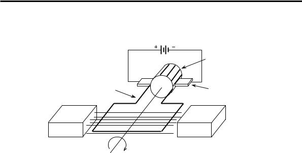
The basic construction of a DC motor is shown in Figure 8-1. Current flows from the power source (shown as a battery) and through the armature coil winding via the brushes in contact with the commutator. This current flow induces a magnetic field around the armature coil that opposes the magnetic field produced by the magnets, and generates a motor torque that is capable of doing work. To produce a smoother output torque, many groups of coil windings are used in a typical motor armature. Each group of windings connects to opposing contacts on the commutator with each commutator contact being insulated from its neighbouring contacts.
Today, permanent magnets are widely used in motors. These magnets are made from Alnico, with high-performance motors using high-strength rare-earth magnets (samarium cobalt).
8 DRIVING MOTORS - DC & STEPPER 199
|
DC Power Supply |
|
Insulator |
|
Armature |
One conductor |
Brush |
Magnet |
Magnet |
N |
S |
Figure 8-1 Basic DC motor construction.
A different type of DC motor, known as the brushless motor, does not have commutator brushes; instead current is switched through the coil windings by electronic means. These motors use permanent magnets for the rotor and have the field windings on the stator. This arrangement gives a greatly improved path for heat flow out of the motor and results in high reliability, low noise, high speed, and high peak torque characteristics.
Motor performance depends upon the load connected to the motor and the applied voltage driving the motor. Friction in the motor bearings, brush losses, iron losses, and short-cut circuit losses (from each brush contact overlapping an adjacent contact) limit the upper speed during no-load situations, and the torque load at the motor shaft determines the lower speed limit. As the load applied to the motor increases, motor speed drops in a linear manner, proportional to the load applied. The steady power produced by the motor can be increased if aircooling is used or if the motor is used for short periods of operation. When selecting a suitable motor for a given task, the load inertia, load torque, and load power should all be considered.
8.2.2 DC Motor Control
To control DC motors, a variable voltage must be generated and applied to power the motor. There are two main sources of voltage supply for a motor: the linear power supply, and the switching power supply. The linear power supply technique uses power transistors acting in their linear mode to provide a smooth and continuously adjustable output voltage depending upon load drive requirements. In this mode, the transistors are used as variable resistors, conducting according to the level of the input signal applied. This method of
200 8 DRIVING MOTORS - DC & STEPPER
control wastes power when the transistors are used to drop voltage and in doing so dissipate power.
Switching power supply techniques use transistors to switch the voltage through to the motor in a series of pulses that applies an ‘average’ voltage to the motor. Two switching methods are commonly used, pulse-width modulation (PWM), and pulse-frequency modulation (PFM) as shown in Figure 8-2.
|
|
|
|
|
T |
|
|
|
|
|
|
T |
||||||
+V |
|
|
|
W |
|
+V |
|
|
|
t |
||||||||
|
|
|
|
|
|
|
time |
|
|
|
|
|
|
|
||||
0V |
|
|
|
|
|
|
|
0V |
|
|
|
|
|
|
|
|||
|
|
|
|
|
|
|
|
|
|
|
||||||||
Pulse-Width Modulation (PWM) |
|
Pulse-Frequency Modulation (PFM) |
||||||||||||||||
Period T is fixed, pulse-width w changes to provide an adjustable ‘average’ output voltage.
Pulse width t is fixed, period T changes to provide an adjustable ‘average’ output voltage.
Figure 8-2 Voltage-control using switching methods.
Pulse-width modulation is the more common method used for motor control. This method uses a constant period (T) between sequential pulses, while the width (w) of the pulses is altered (duty cycle) to change the effective or average voltage applied to the motor.
Pulse-frequency modulation varies the frequency of pulses having a constant pulse width (t) to control the average voltage applied to the motor.
|
|
+V |
SW1 |
|
SW2 |
|
I |
_ |
|
|
|
|
+ |
Motor |
|
|
|
SW3 |
|
I |
|
SW4 |
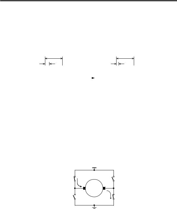
Figure 8-3 Motor control using a H-bridge.
The most common means of controlling the voltage applied to DC motors is through the use of a H-bridge circuit as shown in Figure 8-3. Two switches are
8 DRIVING MOTORS - DC & STEPPER 201
closed at a time to switch the DC voltage through to the motor. When switches designated as SW1 and SW4 are closed and switches SW2 and SW3 are open, as shown in the diagram, the motor will rotate in one direction. Swapping the positions of the open and close switches to make SW2 and SW3 closed and SW1 and SW4 open will reverse the flow of current through the bridge and reverse the direction of motor rotation.
The average voltage delivered to the motor can be controlled using pulse-width modulation applied to the switches. In practice, the switch function is performed using power transistors in place of each switch. As the switch is opened, a large voltage is generated across the motor winding, known as back-emf. This voltage must be limited to avoid damage to the active switching transistors. Damage is prevented by fitting diodes across the transistors that clamp the voltage to much lower levels that will not cause damage.
Motors can be controlled using both openand closed-loop control techniques. Open-loop control does not use any form of feedback from the output of the motor shaft to indicate motor speed or motor shaft rotation. This mode of operation relies upon estimating motor speed or rotation by knowing the motor load and motor operating characteristics. If accurate motor control is needed and motor load is not known or is not constant, closed-loop control is typically used. When controlling motor speed, the feedback taken from the motor output will be motor shaft speed. This is usually measured using a tachometer that generates an output voltage proportional to the motor speed. Alternatively, the tachometer can output a digital pulse-train.
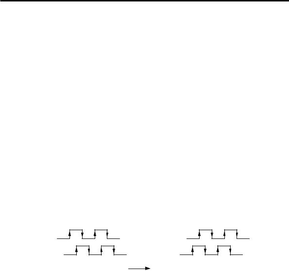
Output A |
|
Output A |
Output B |
|
Output B |
Clockwise Rotation |
time |
Anticlockwise Rotation |
|
Figure 8-4 Motor encoder output – quadrature.
When position control is needed, resolvers or digital encoders are connected to the motor output to provide position feedback. Resolvers generate two out-of-phase sinusoidal waves whose amplitudes provide position information. Optical encoders output two digital waveforms that are separated in phase by approximately 90 degrees to provide directional information in quadrature format as shown in Figure 8-4. It is possible to determine the direction of motor rotation by knowing the order in which the rising or falling edges of each waveform occur.

202 8 DRIVING MOTORS - DC & STEPPER
8.3 Stepper Motors
Stepper motors are often used for motor control applications requiring positive positioning and good levels of torque at low speed. Provided they are not overloaded, their output shaft speed and rotational position are inherently known and controlled through simple digital switching of their winding currents – often without the need for expensive shaft encoders.
8.3.1 Stepper Motor Construction
Three main types of stepper motor construction are in use; these being permanent magnet, variable reluctance, and hybrid construction.
The permanent magnet type has a permanent magnet rotor with many poles. This motor has a residual holding torque when the windings are not energised and requires less power to operate than other types. It is low in cost, produces low torque and runs at low speed. However, it suffers from resonance effects, relatively long settling times and rough performance at low speed. It is mainly used in nonindustrial applications.
Variable reluctance motors use a soft iron core rotor with a different number of teeth than the number of poles on the stator. As the stator poles are energised inturn, the rotor aligns itself with the magnetic field of the energised stator pole, to create a rotor position having minimum magnetic reluctance. This type of motor has a good ratio of torque to inertia but lacks a residual torque when the stator field windings are de-energised. Variable reluctance motors are seldom used in industrial applications and require a different driving arrangement from the other stepper motor types.
Hybrid motors use a combination of permanent magnet and variable reluctance features in their construction. This is the most widely used type of stepper motor for industrial applications due to its high torque and residual holding torque.
8.3.2 Stepper Motor Configuration
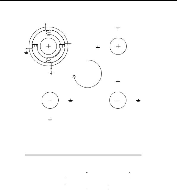
To understand how a stepper motor works, consider the simplified motor shown in Figure 8-5. This motor has a permanent magnet rotor with one north-south pole pair and uses a stator with four teeth. The motor drive sequence shown uses what is known as full-stepping – in this case each full-step corresponds to a 90θ rotation. There are two independent coil windings used on the stator, meaning this is a twophase motor.
The motor rotates in a clockwise direction as shown in Figure 8-5 when using the coil energising sequence in Table 8-1. Both of the motor coils are energised for every step position during each drive sequence.
8 DRIVING MOTORS - DC & STEPPER 203
+Volts
 A1
A1
N
A1
S
|
S |
+ Volts |
|
|
N |
+ Volts |
|
B1 |
|
|
|||
|
|
|
|
|
||
S |
|
N |
B2 |
S |
N |
B1 |
B2 |
N |
|
|
|
S |
|
|
|
|
|
|
||
|
|
|
|
|
N |
|
|
|
|
|
|
A2 |
|
|
S |
|
|
|
+ Volts |
|
|
A2 |
|
Stepping |
|
|
|
|
|
|
|
|
|
|
|
|
|
Sequence |
|
|
|
|
+ Volts |
|
|
|
|
|
|
A1 |
|
|
|
A1 |
|
|
N |
|
|
|
S |
|
|
S |
|
|
|
N |
|
+ Volts B2 N |
|
S B1 |
+ Volts B2 |
N |
S |
B1 |
|
N |
|
|
|
S |
|
|
S |
|
|
|
N |
|
|
A2 |
|
|
|
A2 |
|
+ Volts
Figure 8-5 Simplified 2-phase stepper motor – full-stepping sequence.
Table 8-1 Full-stepping sequence for a 2-phase motor.
Coil Contact Voltage
Step Position |
A1 |
A2 |
B1 |
|
B2 |
|||||||||||||||
1 |
+ |
|
|
|
|
|
+ |
|
|
|
|
|
||||||||
|
|
|
|
|
|
|
|
|
|
|||||||||||
2 |
|
|
|
|
|
+ |
|
+ |
|
|
|
|
|
|||||||
|
|
|
|
|
|
|
|
|
|
|||||||||||
|
|
|
|
|
|
|
|
|
|
|||||||||||
3 |
|
|
|
|
|
+ |
|
|
|
|
|
|
+ |
|||||||
|
|
|
|
|
|
|
|
|
|
|
||||||||||
|
|
|
|
|
|
|
|
|
|
|
||||||||||
4 |
+ |
|
|
|
|
|
|
|
|
|
|
+ |
||||||||
|
|
|
|
|
|
|
|
|
|
|||||||||||
|
|
|
|
|
|
|
|
|
|
|||||||||||
|
|
|
|
|
|
|
|
|
|
|
|
|
|
|
|
|
|
|
|
|
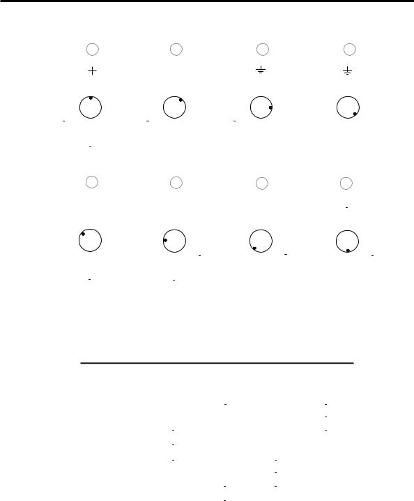
Smaller step angles can be achieved when a half-stepping drive sequence is used. This involves energising only one of the coil windings for every second step angle as shown in Figure 8-6 and Table 8-2.
204 8 DRIVING MOTORS - DC & STEPPER
1 2 3 4
|
|
|
|
|
|
A1 |
|
|
|
|
|
|
|
A1 |
|
|
|
|
|
|
A1 |
|
|
|
A1 |
|||||||||
|
|
|
|
|
|
N |
|
|
|
|
|
|
|
|
|
|
|
|
|
|
|
|
S |
|
|
|
S |
|||||||
|
B2 S |
|
|
|
|
S |
|
|
|
|
|
|
|
|
|
|
|
|
B2 S |
N |
|
|
|
N |
||||||||||
|
|
|
|
|
|
|
|
|
|
|
|
|
|
|
|
|
|
|
|
|||||||||||||||
|
|
|
|
|
|
B1 |
|
|
B2 S N S N B1 |
|
|
B1 |
B2 |
|
|
B1 |
||||||||||||||||||
|
N |
N |
|
|
|
|
|
|
|
N |
|
|
||||||||||||||||||||||
|
|
|
|
|
|
|
|
|
|
|
|
|
|
|
|
|
|
|
|
|
S |
|
|
|
S |
|||||||||
|
|
|
|
|
|
|
|
|
|
|
|
|
|
|
|
|
|
|
|
|
|
|||||||||||||
|
|
|
|
|
|
S |
|
|
|
|
|
|
|
|
|
|
|
|
|
|
|
|
N |
|
|
|
N |
|||||||
|
|
|
|
|
A2 |
|
|
|
|
|
|
|
A2 |
|
|
|
|
|
|
A2 |
|
|
|
A2 |
||||||||||
|
|
|
|
|
|
|
|
|
|
|
|
|
|
|
|
|
|
|
|
|
|
|
|
|
|
|
|
|
|
|
|
|
|
|
|
|
|
|
|
|
|
|
|
|
|
|
|
|
|
|
|
|
|
|
|
|
|
|
|
|
|
|
|
|
|
|
|
|
|
|
|
|
|
|
|
|
|
|
|
|
|
|
|
|
|
|
|
|
|
|
|
|
|
|
|
|
|
|
|
|
|
|
|
|
8 |
|
|
|
|
|
7 |
|
|
|
|
|
|
|
6 |
|
|
|
|
|
|
|
|
|
5 |
|
|
|
|
|
|
|
|
|
|||||||||||
|
|
|
|
|
|
|
|
|
|
|
|
|
|
|
|
|
|
|
|
|
|
|
|
|
|
|
|
|
|
|
|
|
|
|
|
|
|
|
|
|
|
|
|
|
|
|
|
|
|
|
|
|
|
|
|
|
|
|
|
|
|
|
|
|
|
|
|
|
|
|
|
|
|
|
|
|
|
||||||||||||
|
|
A |
1 |
|
|
|
|
|
|
A1 |
|
|
|
|
|
|
|
|
A1 |
|
|
|
|
|
A1 |
|
|
|
|
|
|
|||||||||||||
|
|
N |
|
|
|
|
|
|
N |
|
|
|
|
|
|
|
|
|
|
|
|
|
|
|
|
|
|
|
|
S |
|
|
|
|
|
|
||||||||
|
|
S |
|
|
|
|
S |
|
|
|
|
|
|
|
|
|
|
|
|
|
|
|
|
|
|
|
|
|
|
N |
|
|
|
|
|
|
||||||||
B2 |
B1 |
B2 N |
B1 |
B2 N S N S B1 |
B2 N |
|
|
|
|
|
B1 |
|||||||||||||||||||||||||||||||||
|
|
|
|
S |
|
|
|
|
|
|
S |
|||||||||||||||||||||||||||||||||
|
|
N |
|
|
|
|
|
|
|
N |
|
|
|
|
|
|
|
|
|
|
|
|
|
|
|
|
|
|
S |
|
|
|
|
|
|
|||||||||
|
|
S |
|
|
|
|
|
|
S |
|
|
|
|
|
|
|
|
|
|
|
|
|
|
|
|
|
|
|
|
N |
|
|
|
|
|
|
||||||||
|
A2 |
|
|
|
|
|
|
A2 |
|
|
|
|
|
|
|
|
A2 |
|
|
|
|
A2 |
|
|
|
|
|
|
||||||||||||||||
|
|
|
|
|
|
|
|
|
|
|
|
|
|
|
|
|
|
|
|
|
|
|
|
|
|
|
|
|
|
|
|
|
|
|
|
|
|
|
|
|
|
|
|
|
|
|
|
|
|
|
|
|
|
|
|
|
|
|
|
|
|
|
|
|
|
|
|
|
|
|
|
|
|
|
|
|
|
|
|
|
|
|
|
|
|
|
|
|
|
Figure 8-6 Half-stepping sequence for a 2-phase motor.
Table 8-2 Half-stepping sequence for 2-phase motor.
Coil Contact Voltage
Step Position |
A1 |
A2 |
B1 |
|
B2 |
||||||||||||||||
1 |
+ |
|
|
|
|
|
|
+ |
|
|
|
|
|
||||||||
|
|
|
|
|
|
|
|
|
|
||||||||||||
2 |
|
|
|
|
|
|
+ |
|
+ |
|
|
|
|
|
|||||||
|
|
|
|
|
|
|
|
|
|
|
|
||||||||||
|
|
|
|
|
|
|
|
|
|
|
|
||||||||||
3 |
|
|
|
|
|
|
|
+ |
|
|
|
|
|
||||||||
|
|
|
|
|
|
|
|
|
|
|
|||||||||||
|
|
|
|
|
|
|
|
|
|
|
|||||||||||
4 |
|
|
|
|
|
|
+ |
|
|
|
|
|
|
+ |
|||||||
|
|
|
|
|
|
|
|
|
|
|
|||||||||||
|
|
|
|
|
|
|
|
|
|
|
|||||||||||
5 |
|
|
|
|
|
|
+ |
|
|
|
|
|
|
||||||||
|
|
|
|
|
|
|
|
|
|
|
|||||||||||
6 |
|
|
|
|
|
|
|
|
|
|
|
|
|
|
|
|
+ |
||||
|
|
|
|
|
|
|
|
|
|
|
|
|
|
|
|
||||||
|
|
|
|
|
|
|
|
|
|
|
|
|
|
|
|
||||||
7 |
+ |
|
|
|
|
|
|
|
|
|
|
|
+ |
||||||||
|
|
|
|
|
|
|
|
|
|
||||||||||||
|
|
|
|
|
|
|
|
|
|
||||||||||||
8 |
+ |
|
|
|
|
|
|
|
|
|
|
|
|
|
|
|
|
||||
|
|
|
|
|
|
|
|
|
|
|
|
|
|
|
|||||||
|
|
|
|
|
|
|
|
|
|
|
|
|
|
|
|
||||||
Stepper motors are categorised depending upon the way current is driven through their windings as will now be explained.