

Interfacing with C plus plus-programing communication with microcontrolers (K. Bentley, 2006)
.pdf8 DRIVING MOTORS - DC & STEPPER 215
The motor driving part of the program can be very complex. It may contain sophisticated operations to change the speed, change direction of rotation and to brake the motor. Using virtual functions, the motor control program in the main function can be written completely, without knowing exact specifics of the particular motor to be driven. When the user selects a particular control action for the chosen motor, the correct function from that class will be deployed automatically to operate on the associated object type (without the programmer needing to provide explicit code). When we use virtual functions, the compiler generates the actual code that allows this virtual function mechanism to operate in this way. This behaviour will be shown in the sections ahead. This part of the program will even work for objects that will be added to the class hierarchy in the future. This gives us the flexibility to expand the class hierarchy as desired without needing to rewrite the motor control portion.
When the program is running, the user will select an object type (DCMotor or StepperMotor) to be used from a choice of motor types. For example, the user may select a motor of type DCMotor to be driven forward. Then the program will automatically bind the DCMotor object to the Forward() function of the DCMotor class. This deferred decision-making is known as late binding. In other words, the program selects the correct function to drive the motor forward based on the object type selected by the user at run-time. Late binding is also known as dynamic binding. The word dynamic is used because the binding takes place while the program is running. Note that polymorph functions cannot be used in late binding - only virtual functions can use this feature.
If virtual functions were not used in the program, the programmer would need to provide the extra logic to select the correct function. In this case the end of each logic branch will be hard-coded to bind a specific object to its associated member function. Binding is no longer deferred to a later time. In such a situation the compiler can identify the correct function and bind it at programming time. This is known as early binding or static binding. The word static is used to signify that binding takes place before the program runs - the program is already coded for each possible combination of object/function the user might select.
At first glance, virtual functions and late binding appear to be overkill! However, without them it is very difficult to write sound generic programs that work with a variety of situations that are decided by the user at run time. Using virtual functions can significantly reduce the amount of programming required. The programmer no longer needs to write a number of code segments to control each object type. Instead, one code segment will be written to control all object types of a given hierarchy. Also, the user (or the program itself) has complete flexibility to choose the object type at run time.
8.5.1 Pure Virtual Functions
It was mentioned previously that without knowing the physical construction and interfacing of the motor, it is impossible to define the bodies of the functions
Off(), Forward(), Reverse(), and Brake(). In order to inform the

216 8 DRIVING MOTORS - DC & STEPPER
compiler of our inability to provide the bodies of these functions we must declare them as pure functions. Note that only virtual functions can be declared pure. A function is declared pure by appending ‘=0’ at the end of the declaration.
A normal function is declared as: void Forward();
A virtual function is declared as: virtual void Forward();
A pure virtual function is declared as: virtual void Forward()=0;
Pure Virtual Functions and Abstract Classes
An effect of declaring at least one pure virtual function (which has no executable code) in a class definition is that the class becomes an abstract class. Some abstract classes have useful functions. If the class has a function whose body cannot be defined, then the class cannot be used to instantiate completely usable objects. The reason for this is that a program may attempt to call a pure virtual function (with no executable code). Therefore, a rule is in place that prevents objects from abstract classes being instantiated. We will revisit virtual functions when we make use of them for controlling the DC and Stepper motors in the class hierarchy (shown in Figure 8-14).
Returning to the class definition given previously in Listing 8-1, only three of the member functions can be defined: AbstractMotor(), SetSpeed() and GetSpeed(). As explained previously, the other four functions; Off(), Forward(), Reverse(), and Brake() cannot be defined at this stage, which is why they are declared as pure virtual functions. The member function definitions are given in Listing 8-2.
Listing 8-2 AbstractMotor class member function definitions.
AbstractMotor::AbstractMotor()
{
Speed =0;
}
void AbstractMotor::SetSpeed(int speed)
{
Speed = speed;
if(Speed > 255) Speed = 255; // Limit upper value if(Speed < 0) Speed = 0; // Limit lower value
}
int AbstractMotor::GetSpeed()

8 DRIVING MOTORS - DC & STEPPER 217
{
return Speed;
}
The constructor of the AbstractMotor class initialises the data member Speed to 0.
The public function Setspeed() can be called by any function to change the speed of any of the motors in the hierarchy. This function assigns the actual argument passed in speed to the member data Speed. The two if statements in the SetSpeed() function ensure the actual argument passed in place of speed is restricted to within the acceptable range 0 – 255 we have decided to use. If for example, a value such as 300 is passed, then the first if statement will limit and override that value to become 255. Therefore, the data member Speed will be set to 255. In other words, any value above 255 will be forced to be 255. The second if statement will force any value below 0 to be 0. Any value inside the acceptable range will be left as is.
The GetSpeed() function returns the current value of Speed to any function. This is the only mechanism provided for a function outside the class to obtain the value of Speed.
Motor Class
Next in the class hierarchy is the Motor class. This class inherits functions and data from the two classes AbstractMotor and ParallelPort. Its class definition is given in Listing 8-3.
Listing 8-3 Motor class.
class Motor : public AbstractMotor, public ParallelPort
{
public:
Motor(int baseaddress=0x378); void Off();
virtual void Forward()=0; virtual void Reverse()=0; virtual void Brake()=0;
};
Note the program line:
class Motor : public AbstractMotor, public ParallelPort
The new class name is Motor and it is derived using the public access specifier with the two base classes AbstractMotor and ParallelPort. A comma separates the base classes. No new data members are added. The two functions that
218 8 DRIVING MOTORS - DC & STEPPER
must be defined are the constructor of the Motor class and the Off() function. The other three functions remain as pure virtual functions. It was mentioned earlier that if at least one of the member functions is a pure virtual function, the class becomes an abstract class. Therefore the Motor class is an abstract class and so cannot be used to instantiate objects. The difference between the classes AbstractMotor and Motor is that the latter has the ability to communicate with devices via the parallel port. As such, any objects derived from the Motor class can communicate via the parallel port.
The definition of the Motor class constructor and the Off() function is given in Listing 8-4.
Listing 8-4 Member function definitions for the Motor class.
Motor::Motor(int baseaddress):ParallelPort(baseaddress)
{
Off();
}
void Motor::Off()
{
WritePort0(0x00);
}
All motors can be controlled using either one or both H-bridge circuits on the interface board. Each H-bridge circuit uses four ‘switches’ with a corresponding logic control signal for each switch. Therefore, to control both H-bridges requires eight control signals, and so our programs will use the port at address BASE for this purpose.
A motor can be turned off by opening switches in the H-bridge. For DC motors, open all four switches, and for bipolar stepper motors, open all eight switches of the two H-bridges. In general, we can turn off any type of motor by opening all eight switches of the two H-bridges if we set all eight bits of the port at address BASE to zero. The Off() function does just this. It is not a virtual function since none of the derived classes require further specialisation of this function.
Note that the constructor calls the Off() function. This turns all transistors off in both H-bridges to eliminate any risk of a short-circuit path being generated between the power supply positive output and its ground return. This means that the user must allow the program to execute before connecting power to the interface board and motor.
Default Parameter Values for Functions
The constructor for the Motor class is an improvement on the coding of the constructors for the classes in previous chapters. These earlier chapters used a default constructor that took no parameters, and a constructor that took an
8 DRIVING MOTORS - DC & STEPPER 219
argument of type integer for the baseaddress parameter. The constructor Motor(int baseaddress=0x378) takes a parameter to be passed to the base class constructor ParallelPort(int baseaddress) and it initialises the value of this parameter to 0x378 if no argument is provided when instantiating the Motor object. This allows this single constructor to perform the role of the two different constructors used in earlier chapters.
The default parameter value for baseaddress is shown in bold typeface in Listing 8-3. As implied by the word ‘default’, if no actual argument is passed when declaring an instance of an object, the actual argument will be taken as 0x378. Note that the default argument value is mentioned within the pair of parentheses of the constructor in the class definition (Listing 8-3). This is one way to specify default actual argument values. Another method for specifying default arguments is to include them in the function definition as shown in Figure 8-15. In this case we do not specify the default actual argument values in the class definition as is shown in Listing 8-5. Note that we must not specify default values in both places!
Motor::Motor(int baseaddress=0x378):AbstractMotor(), ParallelPort(baseaddress)
{
|
Off(); |
Default actual argument for the |
|
} |
parameter baseaddress |
||
|
|||
|
|
Figure 8-15 An alternative way of specifying default actual argument values.
Listing 8-5 Motor class definition with no default arguments specified inside.
class Motor : public AbstractMotor, public ParallelPort
{
public:
Motor(int baseaddress); void Off();
virtual void Forward(int speed)=0; virtual void Reverse(int speed)=0; virtual void Brake()=0;
};
The Motor class constructor can be called in one of the two following forms as shown in Figure 8-16 and Figure 8-17:

220 8 DRIVING MOTORS - DC & STEPPER
Motor();
No actual argument is passed, therefore the default argument is used. As a result the inherited data member BaseAddress will become 0x378.
Figure 8-16 Calling the Motor class constructor without arguments.
Motor(0x3BC);
 An actual argument is passed. As a result the inherited data member BaseAddress will become 0x3BC.
Figure 8-17 Calling the Motor class constructor with an actual argument.
The function Motor() being a constructor, can also be called in the manner shown in Figure 8-18.
Motor;
For a constructor, the pair of parentheses can be dropped. The result is identical to that for Figure 8-16.
Figure 8-18 Calling a constructor with default actual arguments.
These examples show how one parameter can be given a default actual argument. If the function has more than one parameter, any of them can be assigned default actual arguments subject to the following condition. All parameters to the right of the parameter being considered must also have default actual argument values assigned. The two examples in Figure 8-19 show the valid and invalid declarations.
void |
AnyFunction(int |
x, |
int |
y=0, |
int |
z=1); |
// |
correct |
|
This situation is acceptable. Parameter y can be assigned a default actual argument |
|||||||
|
value because parameter z is already assigned a default actual argument value. |
|||||||
void |
AnyFunction(int |
x, |
int |
y=0, |
int |
z); |
// |
illegal |
This situation is illegal. Parameter y cannot be assigned a default actual argument value because parameter z has not been assigned a default actual argument value.
Figure 8-19 Assigning multiple default actual arguments.
8 DRIVING MOTORS - DC & STEPPER 221
DCMotor class
The DCMotor class is at the bottom end of the class hierarchy shown in Figure 8-14. This class is developed to represent real DC motors. As such, the class is no longer an abstract class. The class definition for the DCMotor class is given in Listing 8-6.
Listing 8-6 DCMotor class.
class DCMotor : public Motor
{
public:
DCMotor(int baseaddress=0x378); virtual void Forward();
virtual void Reverse(); virtual void Brake();
};
The DCMotor class is derived from the Motor class. Although the DCMotor class looks small, it has inherited all member data and member functions from the Motor, AbstractMotor, and ParallelPort classes in the hierarchy. Note that there are no pure virtual functions in the class definition for the DCMotor class. Therefore, the class is not an abstract class, but a real class that can be used to instantiate objects once complete function definitions are provided.
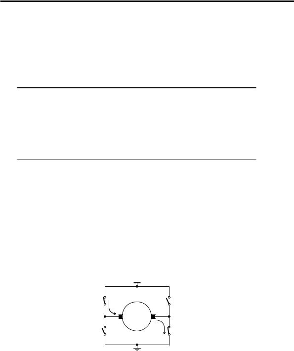
To be able to define the member functions of the class, we must know how to drive the DC motor and connect it to the interface board. Figure 8-20 shows how a DC motor is connected using a H-bridge. We can use the data bits D0 to D3 of the port at BASE address to control the switches SW1 to SW4 as shown in Table 8-7.
|
|
|
+Vm |
SW1 |
|
|
SW2 |
(A) |
I |
|
(B) |
|
|
|
_ |
|
|
+ |
Motor |
|
|
|
|
SW3 |
|
|
I |
|
|
SW4 |
|
(C) |
|
|
(D) |
Figure 8-20 H-bridge connections to a DC Motor.

222 8 DRIVING MOTORS - DC & STEPPER
Table 8-7 DC Motor H-bridge to Parallel Port connections (Figure 8-20).
|
H-bridge label on |
BASE Address |
Switch No |
Interface Board |
Data Bit |
|
|
|
SW1 |
A |
D0 |
SW2 |
B |
D1 |
SW3 |
C |
D2 |
SW4 |
D |
D3 |
|
|
|
A data-bit set to 1 closes the switch, whereas a 0 opens the switch. To drive the motor forward, the data bits D0 and D3 must be set to 1 and bits D1 and D2 must be set to 0. To drive the motor in reverse, we must do the opposite, i.e. data bits D1 and D2 must be set to 1 and data bits D0 and D3 must be set to 0.
To brake the motor, short-circuit the ends of the armature together. This can be done by either setting bits D0 and D1 to 1 (D2, D3 set to 0), or by setting bits D2 and D3 to 1 (D0, D1 set to 0). We will choose to short-circuit the armature to ground. For this, bits D2 and D3 will be set to 1 and bits D0 and D1 will be set to zero. Table 8-8 summarises the values to be written to the port to achieve forward motion, reverse motion and braking.
Table 8-8 Data to be written to the port to control the DC motor.
Operation |
|
|
|
Data Bits† |
|
|
|
Output to port at |
||
D7 |
D6 |
D5 |
D4 |
D3 |
D2 |
D1 |
D0 |
address BASE |
||
|
||||||||||
Forward |
x |
x |
x |
x |
1 |
0 |
0 |
1 |
0000 1001 = 0x09 |
|
Reverse |
x |
x |
x |
x |
0 |
1 |
1 |
0 |
0000 0110 = 0x06 |
|
Brake |
x |
x |
x |
x |
1 |
1 |
0 |
0 |
0000 1100 = 0x0C |
|
† data bits represented as ‘x’ can take either 0 or 1. They are not connected to the H-bridge to drive a DC motor, and so do not have any effect. They have been taken to be 0 for bits D4 to D7.
WARNING
Do NOT at any time allow SW1 and SW3 to be turned on together at anytime.
Likewise, do NOT at any time allow SW2 and SW4 to be turned on together. If
these events were allowed to happen, the transistors and possibly the power supply will be damaged.
The DC motor is connected to the interface board as shown in Table 8-9 and Figure 8-21. The interface board is designed to drive +12V DC motors that require less than 1A of current. However, DC motors can be driven from external DC power supplies (up to a maximum 30V) as explained in the following note. Leave the
8 DRIVING MOTORS - DC & STEPPER 223
interface board unpowered until the program is being executed since some bits of the port to be used may have previously been left in an on state.
NOTE
The two contacts on the 4-way terminal block labelled VM1 and VM1 GND are
used to connect power to the H-bridge (VM2 and VM2 GND for the other H- bridge).
The interface board is capable of providing +12V at up to 1A to drive motors. To
use this power supply, connect Vm1 (or Vm2 as appropriate) via an insulated wire
to the +12V of the power supply’s 2-way terminal block (where the power-pack
connects). A second insulated wire is used to connect the ground of the respective
H-bridge Vm1 GND (or Vm2 GND) to the ground of the power supply. Most
importantly, a wire needs to be connected across the two contacts of each 2-way terminal block. These 2-way terminal blocks have been provided to allow resistive drive schemes to be trialed by fitting resistors of suitable value inplace of the
wires.
Motors may need to be driven with voltage or current supply requirements differing
from those of the power supply on the interface board (+12V, 1A). In this case, an
external power supply up to a maximum of 30 V DC can be used to power the
motors. DO NOT at any time attempt to connect mains power to the board.
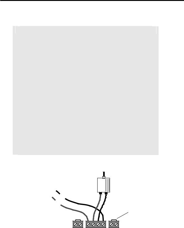
When using an external power supply, connect the positive contact of its output to the 4-way terminal block contact Vm1 (or Vm2 as appropriate). Also, connect the
negative contact of the external power supply to the 4-way terminal block contact
Vm1 GND (or Vm2 GND). The external power supply MUST NOT be connected to
the 2-way terminal block of the interface board power supply.
+12V (1A) power supply’s
2-way terminal block
OR - VE
External |
+ VE |
DC Power Supply |
|
(Max 30V) |
|
Vm1 M1 M2 |
Vm1 GND |
Wire Link
J7 |
J6 |
J8 |
Figure 8-21 Connecting a DC power supply to power a DC motor.
224 8 DRIVING MOTORS - DC & STEPPER
Table 8-9 H-bridge to DC motor connections.
H Bridge 1 |
Connections |
Vm1 |
Motor Power Supply +ve* |
M1 |
Motor + terminal |
M2 |
Motor - terminal |
Vm1 GND |
Motor Power Supply –ve* |
Having determined all the connections, we can now proceed to implement a method to drive the motor, in particular to control its torque/speed. The most appropriate means to do this is by using Pulse Width Modulated (PWM) signals.
8.5.2 Generating Pulse Width Modulated Signals
As described earlier in Section 8.2.2, using pulse width modulation with wider pulse widths generates higher levels of motor speed/torque. In other words, the higher the duty cycle, the higher the motor speed. In our application the duty cycle is the proportion of time in a repetitive cycle that the motor will have power applied to it. This ratio is usually represented as a percentage. To control the speed we must control the duty cycle. Therefore, the design of the program should allow the duty cycle to be changed as desired. In general, exact timing is normally used to control duty cycle. In this chapter, we will not use exact time delays. Instead, duty cycle will be controlled by executing software loops. Different computers will have different execution speeds and therefore produce different PWM cycle times (frequencies), although the shape/duty cycle of the PWM signal will be the same.
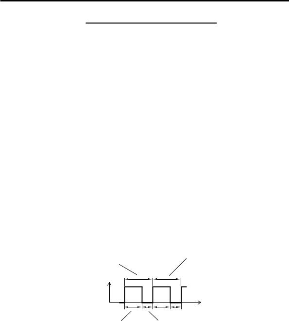
Single PWM cycle, comprising 256 writes to the port at BASE address. The actual cycle time is determined by the speed of your computer.
Next PWM cycle. These cycles repeat continuously to generate a PWM signal.
Voltage
Time
N writes of 0x09 to the port thereby applying full voltage to the armature of the DC motor.
(256-N) writes of 0x00 to the port thereby removing the voltage to the armature.
Figure 8-22 Generation of a PWM signal.
The PWM signal can be generated as follows. Suppose one cycle consists of 256 uninterrupted writes to the port. The cycle time is then equal to the time the