

17.3 Generic antenna types
17.3.1 Radiation from apertures
The
radiation from apertures illustrates most of the significant
properties
of pencil beam antennas. The radiation characteristics can be
determined by simple mathematical relationships. If the electric
fields across an aperture, Figure 17.4, is Ea(x,y)
then the
radiated fields
![]() is given by Equation 17.3, where
is given by Equation 17.3, where![]() is given by Equation 17.4. (Oliver, 1986; Milligan, 1985).
is given by Equation 17.4. (Oliver, 1986; Milligan, 1985).

For high or medium gain antennas the pencil beam radiation is largely focused to a small range of angles around 0 = 0. In this case it can be seen from Equation 17.3 that the distant radiated fields, and the aperture fields are the Fourier transformation of each other. Fourier transforms have been widely studied and their properties can be used to understand the radiation characteristics of aperture antennas. Simple aperture distributions have analytic Fourier transforms, whilst more complex distributions can be solved numerically on a computer.
The
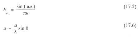
simplest aperture is a one dimensional line source distribution of
length
![]() This serves to illustrate many of the features of aperture
antennas. If the field in the aperture is constant, the radiated
field
is given from Equation 17.3 as in Equations 17.5 and 17.6.
This serves to illustrate many of the features of aperture
antennas. If the field in the aperture is constant, the radiated
field
is given from Equation 17.3 as in Equations 17.5 and 17.6.
width
and is
![]() .The
first sidelobe level is at -13.2dB which is a disadvantage
of a uniform aperture distribution. The level can be reduced
considerably by a tapered aperture distribution where the field is
greatest at the centre of the aperture and tapers to a lower level
at the edge of the aperture. For example if Equation 17.7 holds, then
the first sidelobe level is at -23dB.
.The
first sidelobe level is at -13.2dB which is a disadvantage
of a uniform aperture distribution. The level can be reduced
considerably by a tapered aperture distribution where the field is
greatest at the centre of the aperture and tapers to a lower level
at the edge of the aperture. For example if Equation 17.7 holds, then
the first sidelobe level is at -23dB.
![]()
The
energy which was in the sidelobes moves to the main beam with
the result that the beamwidth broadens to
![]() .
In practicealmost
all antennas have natural tapers across the aperture which result
from boundary conditions and waveguide modes. Rectangular
apertures are formed from two line source distributions in
orthogonal
planes.
.
In practicealmost
all antennas have natural tapers across the aperture which result
from boundary conditions and waveguide modes. Rectangular
apertures are formed from two line source distributions in
orthogonal
planes.
Circular apertures form the largest single class of aperture antennas. The parabolic reflector is widely used in communications and is often fed by a conical horn. Both the reflector and the horn are circular apertures. For an aperture distribution which is independent of azimuthal angle the simplest case is uniform illumination which gives a radiated field as in Equation 17.8, where J1 (x) is a Bessel function of zero order.
![]()
![]() and
is also plotted i n Figure 17.5.
and
is also plotted i n Figure 17.5.
The
first sidelobe level is at-17.6dB. Table 17.2 lists a number of
circular aperture distributions and corresponding radiation pattern
properties. The pedestal distribution is representative of many
reflector
antennas which have an edge tapers of about -10 dB corresponding
to
![]() .The
Gaussian distribution is also
important
because high performance teed horns ideally have Gaussian
aperture distributions. The Fourier transform of a Gaussian taper
which decreases to zero at the edge of the aperture gives a Gaussian
radiation pattern which has no sidelobes.
.The
Gaussian distribution is also
important
because high performance teed horns ideally have Gaussian
aperture distributions. The Fourier transform of a Gaussian taper
which decreases to zero at the edge of the aperture gives a Gaussian
radiation pattern which has no sidelobes.