

- •About the Authors
- •Dedication
- •Authors’ Acknowledgments
- •Table of Contents
- •Introduction
- •What’s Not (And What Is) in This Book
- •Mac attack!
- •Who Do We Think You Are?
- •How This Book Is Organized
- •Part I: AutoCAD 101
- •Part II: Let There Be Lines
- •Part III: If Drawings Could Talk
- •Part IV: Advancing with AutoCAD
- •Part V: On a 3D Spree
- •Part VI: The Part of Tens
- •But wait . . . there’s more!
- •Icons Used in This Book
- •A Few Conventions — Just in Case
- •Commanding from the keyboard
- •Tying things up with the Ribbon
- •Where to Go from Here
- •Why AutoCAD?
- •The Importance of Being DWG
- •Seeing the LT
- •Checking System Requirements
- •Suddenly, It’s 2013!
- •AutoCAD Does Windows (And Office)
- •And They’re Off: AutoCAD’s Opening Screens
- •Running with Ribbons
- •Getting with the Program
- •Looking for Mr. Status Bar
- •Let your fingers do the talking: The command window
- •The key(board) to AutoCAD success
- •Keeping tabs on palettes
- •Down the main stretch: The drawing area
- •Fun with F1
- •A Simple Setup
- •Drawing a (Base) Plate
- •Drawing rectangles on the right layers
- •Circling your plate
- •Nuts to you
- •Getting a Closer Look with Zoom and Pan
- •Modifying to Make It Merrier
- •Hip-hip-array!
- •Stretching out
- •Crossing your hatches
- •Following the Plot
- •A Setup Roadmap
- •Choosing your units
- •Weighing up your scales
- •Thinking annotatively
- •Thinking about paper
- •Defending your border
- •A Template for Success
- •Making the Most of Model Space
- •Setting your units
- •Making the drawing area snap-py (and grid-dy)
- •Setting linetype and dimension scales
- •Entering drawing properties
- •Making Templates Your Own
- •Setting Up a Layout in Paper Space
- •Will that be tabs or buttons?
- •View layouts Quick(View)ly
- •Creating a layout
- •Copying and changing layouts
- •Lost in paper space
- •Spaced out
- •A view(port) for drawing in
- •About Paper Space Layouts and Plotting
- •Managing Your Properties
- •Layer one on me!
- •Accumulating properties
- •Creating new layers
- •Manipulating layers
- •Using Named Objects
- •Using AutoCAD DesignCenter
- •Copying layers between drawings
- •Controlling Your Precision
- •Keyboard capers: Coordinate input
- •Understanding AutoCAD’s coordinate systems
- •Grab an object and make it snappy
- •Other Practical Precision Procedures
- •Introducing the AutoCAD Drawing Commands
- •The Straight and Narrow: Lines, Polylines, and Polygons
- •Toeing the line
- •Connecting the lines with polyline
- •Squaring off with rectangles
- •Choosing your sides with polygon
- •(Throwing) Curves
- •Going full circle
- •Arc-y-ology
- •Solar ellipses
- •Splines: The sketchy, sinuous curves
- •Donuts: The circles with a difference
- •Revision clouds on the horizon
- •Scoring Points
- •Commanding and Selecting
- •Command-first editing
- •Selection-first editing
- •Direct object manipulation
- •Choosing an editing style
- •Grab It
- •One-by-one selection
- •Selection boxes left and right
- •Perfecting Selecting
- •AutoCAD Groupies
- •Object Selection: Now You See It . . .
- •Get a Grip
- •About grips
- •A gripping example
- •Move it!
- •Copy, or a kinder, gentler Move
- •A warm-up stretch
- •Your AutoCAD Toolkit
- •The Big Three: Move, Copy, and Stretch
- •Base points and displacements
- •Move
- •Copy
- •Copy between drawings
- •Stretch
- •More Manipulations
- •Mirror
- •Rotate
- •Scale
- •Array
- •Offset
- •Slicing, Dicing, and Splicing
- •Trim and Extend
- •Break
- •Fillet and Chamfer and Blend
- •Join
- •When Editing Goes Bad
- •Zoom and Pan with Glass and Hand
- •The wheel deal
- •Navigating your drawing
- •Controlling your cube
- •Time to zoom
- •A View by Any Other Name . . .
- •Looking Around in Layout Land
- •Degenerating and Regenerating
- •Getting Ready to Write
- •Simply stylish text
- •Taking your text to new heights
- •One line or two?
- •Your text will be justified
- •Using the Same Old Line
- •Turning On Your Annotative Objects
- •Saying More in Multiline Text
- •Making it with Mtext
- •It slices; it dices . . .
- •Doing a number on your Mtext lists
- •Line up in columns — now!
- •Modifying Mtext
- •Gather Round the Tables
- •Tables have style, too
- •Creating and editing tables
- •Take Me to Your Leader
- •Electing a leader
- •Multi options for multileaders
- •How Do You Measure Up?
- •A Field Guide to Dimensions
- •The lazy drafter jumps over to the quick dimension commands
- •Dimension associativity
- •Where, oh where, do my dimensions go?
- •The Latest Styles in Dimensioning
- •Creating and managing dimension styles
- •Let’s get stylish!
- •Adjusting style settings
- •Size Matters
- •Details at other scales
- •Editing Dimensions
- •Editing dimension geometry
- •Editing dimension text
- •Controlling and editing dimension associativity
- •Batten Down the Hatches!
- •Don’t Count Your Hatches. . .
- •Size Matters!
- •We can do this the hard way. . .
- •. . . or we can do this the easy way
- •Annotative versus non-annotative
- •Pushing the Boundary (Of) Hatch
- •Your hatching has no style!
- •Hatch from scratch
- •Editing Hatch Objects
- •You Say Printing, We Say Plotting
- •The Plot Quickens
- •Plotting success in 16 steps
- •Get with the system
- •Configure it out
- •Preview one, two
- •Instead of fit, scale it
- •Plotting the Layout of the Land
- •Plotting Lineweights and Colors
- •Plotting with style
- •Plotting through thick and thin
- •Plotting in color
- •It’s a (Page) Setup!
- •Continuing the Plot Dialog
- •The Plot Sickens
- •Rocking with Blocks
- •Creating Block Definitions
- •Inserting Blocks
- •Attributes: Fill-in-the-Blank Blocks
- •Creating attribute definitions
- •Defining blocks that contain attribute definitions
- •Inserting blocks that contain attribute definitions
- •Edit attribute values
- •Extracting data
- •Exploding Blocks
- •Purging Unused Block Definitions
- •Arraying Associatively
- •Comparing the old and new ARRAY commands
- •Hip, hip, array!
- •Associatively editing
- •Going External
- •Becoming attached to your xrefs
- •Layer-palooza
- •Creating and editing an external reference file
- •Forging an xref path
- •Managing xrefs
- •Blocks, Xrefs, and Drawing Organization
- •Mastering the Raster
- •Attaching a raster image
- •Maintaining your image
- •Theme and Variations: Dynamic Blocks
- •Lights! Parameters!! Actions!!!
- •Manipulating dynamic blocks
- •Maintaining Design Intent
- •Defining terms
- •Forget about drawing with precision!
- •Constrain yourself
- •Understanding Geometric Constraints
- •Applying a little more constraint
- •AutoConstrain yourself!
- •Understanding Dimensional Constraints
- •Practice a little constraint
- •Making your drawing even smarter
- •Using the Parameters Manager
- •Dimensions or constraints — have it both ways!
- •The Internet and AutoCAD: An Overview
- •You send me
- •Send it with eTransmit
- •Rapid eTransmit
- •Bad reception?
- •Help from the Reference Manager
- •Design Web Format — Not Just for the Web
- •All about DWF and DWFx
- •Autodesk Design Review 2013
- •The Drawing Protection Racket
- •Autodesk Weather Forecast: Increasing Cloud
- •Working Solidly in the Cloud
- •Free AutoCAD!
- •Going once, going twice, going 123D
- •Your head planted firmly in the cloud
- •The pros
- •The cons
- •Cloudy with a shower of DWGs
- •AutoCAD 2013 cloud connectivity
- •Tomorrow’s Forecast
- •Understanding 3D Digital Models
- •Tools of the Trade
- •Warp speed ahead
- •Entering the third dimension
- •Untying the Ribbon and opening some palettes
- •Modeling from Above
- •Using 3D coordinate input
- •Using point filters
- •Object snaps and object snap tracking
- •Changing Planes
- •Displaying the UCS icon
- •Adjusting the UCS
- •Navigating the 3D Waters
- •Orbit à go-go
- •Taking a spin around the cube
- •Grabbing the SteeringWheels
- •Visualizing 3D Objects
- •Getting Your 3D Bearings
- •Creating a better 3D template
- •Seeing the world from new viewpoints
- •From Drawing to Modeling in 3D
- •Drawing basic 3D objects
- •Gaining a solid foundation
- •Drawing solid primitives
- •Adding the Third Dimension to 2D Objects
- •Creating 3D objects from 2D drawings
- •Modifying 3D Objects
- •Selecting subobjects
- •Working with gizmos
- •More 3D variants of 2D commands
- •Editing solids
- •Get the 2D Out of Here!
- •A different point of view
- •But wait! There’s more!
- •But wait! There’s less!
- •Do You See What I See?
- •Visualizing the Digital World
- •Adding Lighting
- •Default lighting
- •User-defined lights
- •Sunlight
- •Creating and Applying Materials
- •Defining a Background
- •Rendering a 3D Model
- •Autodesk Feedback Community
- •Autodesk Discussion Groups
- •Autodesk’s Own Bloggers
- •Autodesk University
- •The Autodesk Channel on YouTube
- •The World Wide (CAD) Web
- •Your Local ATC
- •Your Local User Group
- •AUGI
- •Books
- •Price
- •3D Abilities
- •Customization Options
- •Network Licensing
- •Express Tools
- •Parametrics
- •Standards Checking
- •Data Extraction
- •MLINE versus DLINE
- •Profiles
- •Reference Manager
- •And The Good News Is . . .
- •APERTURE
- •DIMASSOC
- •MENUBAR
- •MIRRTEXT
- •OSNAPZ
- •PICKBOX
- •REMEMBERFOLDERS
- •ROLLOVERTIPS
- •TOOLTIPS
- •VISRETAIN
- •And the Bonus Round
- •Index
15
Down the Hatch!
In This Chapter
Adding hatching to your drawings
Using predefined and user-defined hatch patterns
Making solid fills
Choosing hatching boundaries
Using annotative hatching
Copying existing hatches
Editing hatches
If you were hoping to hatch a plot (or plot a hatch), see Chapter 16. If you want to hatch an egg, look for Raising Chickens For Dummies, by
Kimberly Willis and Robert T. Ludlow. If you need to fill in closed areas of your drawings with special patterns of lines (crosshatching, or more commonly just hatching) or solid fills,
this is your chapter.
An AutoCAD hatch is a separate object that fills a space; has an appearance dictated by the hatch pattern assigned to it; and by default is associated with the objects that bound the space, such as lines, polylines, or arcs. If you move or stretch the boundaries, AutoCAD normally updates the hatching to fill the resized area.
Batten Down the Hatches!
Drafters often use hatching to represent the type of material
that makes up an object, such as insulation, metal, and concrete. In other cases, hatching helps emphasize or clarify the extent of a particular element in the drawing — for example, showing the location of walls in a
www.it-ebooks.info

324 Part III: If Drawings Could Talk
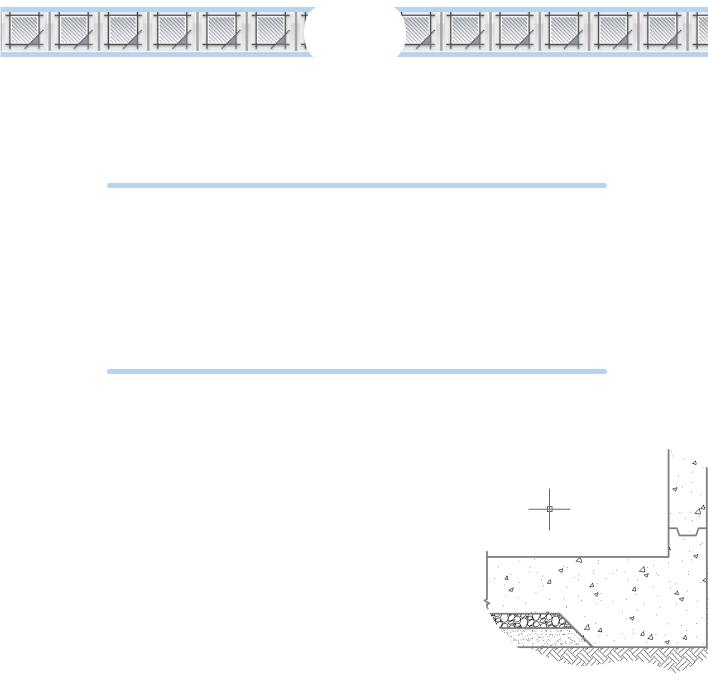
building plan or highlighting a swampy area on a map so you know where to avoid building a road. Figure 15-1 shows an example of hatching in a structural detail. In mechanical design, it’s used to show the cut faces of cross sections.
Figure 15-1: A big batch o’ hatch.
This section gives you a quick jump-start on the basic process used to create hatching and shows you how easy it is. We’ll also cover many of the options included in the Hatch Creation contextual Ribbon tab, shown in Figure 15-2, and how to edit existing hatched areas.
The following steps show you how to hatch an enclosed area by using the pick points method of selecting the hatch area:
1.Start a new drawing, using the acad.dwt template for imperial units or acadISO.dwt for metric.
Draw a circle with a radius of 5 units (imperial) or 50 units (metric). Draw a second circle inside the first with a radius of 2 units (imperial) or 20 units (metric).
2.Start the HATCH command by typing H and pressing Enter, or click the Hatch button on the Draw panel of the Ribbon’s Home tab.
The Hatch Creation contextual Ribbon tab (see Figure 15-2) appears, but just ignore it for the time being.
www.it-ebooks.info

Chapter 15: Down the Hatch! 325
3.Move the cursor around on the screen.
As the cursor moves within any enclosed area in your drawing, a quick preview appears to show you how the final hatching would look like if you picked a point inside that particular area. Starting from outside the larger circle, move it into the space between circles; then into the inner circle, and then back into the space between circles — and note the changes.
4.Change some of the hatch options.
The quick preview updates as you select any variants or change any values in the Hatch Ribbon panels. Try different patterns. The three little arrows along the right side of the Pattern panel scroll you through all the different patterns that are available. Our personal favorite is Escher.
5.Pick a point in the region between the circles.
Press Enter or the spacebar, or right-click and then click Enter.
Congratulations! You’ve just done — in a few seconds — something that would have taken an hour or more in pencil-and-paper days.
But wait! There’s more!
6.Time for a change.
Click the outer circle, and then click and drag one of the four outer grips to change the diameter of the circle. Watch in shock and awe as the hatching updates to match. This is associative hatching.
Now click the inner circle, and then click and drag its center grip to change its location. What happens when you move the smaller one outside the larger one? And what happens when you move it back inside?
Figure 15-2: The Hatch Creation contextual Ribbon tab.
Don’t Count Your Hatches. . .
Now that you’ve seen how easy it is to create hatched areas, explore the main options within the contextual Hatch tabs of the Ribbon. If you start the HATCH command, you get the Hatch Creation tab you used previously. But if you double-click an existing hatch, you get the Hatch Edit tab — they are virtually identical.
www.it-ebooks.info

326 Part III: If Drawings Could Talk
Working from left to right, you find:
Boundaries
If you followed the earlier example in this chapter, you already used the easiest, most intuitive, and most common way of defining the boundary of a hatch when you simply picked inside the desired region. If you pick multiple regions within one run of the HATCH command, each region
is hatched, and the result is one hatch object. This means that later, when you edit the properties of any region, all regions are updated. This is commonly used when hatching the cut faces of a cross section; all faces common to a single item automatically maintain matching hatch properties.
You can also select an area to be hatched by picking specific objects to define the boundary, but you must select enough objects to define a fully enclosed region. In the previous section, our pick points exercise shows how the hatch pattern behaves when you select the region between the circles — it doesn’t hatch the inner circle. This is island detection. If you select specific objects for the boundary, island detec-
tion is turned off. In the exercise, if you had selected the outer circle, the hatching would run right over the inner circle.
No matter which selection method you choose, the boundary must be airtight. Boundary objects can overlap, but there can’t be any leaks, not even microscopic ones. Okay, technically, it is possible to set a fuzz factor to allow for very tiny leaks, but because this defeats the purpose of drawing with precision, we’re not going to tell you about it.
The A Closed Boundary Could Not Be Determined error message means that you need to repair lines or other objects so they define a fully airtight boundary. Sometimes you can use the FILLET command with a 0 (zero) fillet radius to force two lines to meet exactly. Another possibility is to use grip editing to align one endpoint precisely with another. Chapters 10 and 11 discuss these two editing techniques. The HATCH command displays one or more red circles at gaps in the not-quite- enclosed area you want to hatch. Even if it won’t fix the gaps, it does show you where you should fix them.
Moving right along, the next panel in the Hatch tab is Pattern.
Pattern
If you think a bride planning a wedding has a wide range of patterns to choose from, take a peek at AutoCAD’s collection of hatch patterns. The scroll arrows at the right-hand edge of this panel give access to the 82 predefined hatch patterns, including 9 solid and gradient fills that ship with AutoCAD.
www.it-ebooks.info

Chapter 15: Down the Hatch! 327
Hatch patterns are defined by external files named acad.pat or
acadlt.pat (imperial units), or acadiso.pat or acadltiso.pat
(metric units). Each file includes the definitions for all the patterns. You can also create your own hatch patterns — the online help system’s Customization Guide explains how — or you can buy libraries of custom hatch patterns. Any patterns not defined in acad.pat or acadiso.pat are referred to as custom patterns, but you must be careful when using them. Because they are external files, they must be available to AutoCAD when you open a drawing containing them. If you send the drawing to someone else, you must also send the pattern definition file, which can have copyright issues if you bought the patterns.
Autodesk created the hatch patterns whose names begin with AR- particularly for use in architectural drawings, and unlike the non-AR patterns, they do represent real objects such as brick and roof shakes. The AR patterns were designed with a final hatch scale of 1.0 in mind, but in some cases, you’ll have to adjust up or down in order to achieve a suitable scale.
Properties
This panel contains buttons for as many as ten different properties that can be attached to hatches, but many of them can be covered in other ways. We identify them by their default values. Your results may differ.
•Pattern: See the Pattern panel.
•Use Current: This button refers to color, and should nearly always be ByLayer, which is what the current general color override should be.
•None: This button refers to background color, which can be useful when using hatching to portray actual objects. For example, a brick pattern could have a red background so the hatched region looks like red bricks, as shown in Figure 15-3.
•Hatch Transparency: The options for this button range from 0 (opaque) to 90% transparent.
•Angle: Hatch patterns can be rotated as desired. For example, in mechanical design, you may be cutting a cross section of an assembly. Standard practice is to hatch the resultant cut faces,
usually with ANSI31, and to adjust the rotation angles so that each part has a different angle to help distinguish one from another. Note that some patterns — the ANSI series, in particular — usually have an initial 45-degree rotation built in.
•Scale: Ah, here’s the big one (pun intended). We cover it in more detail in the “Size Matters!” section, a little later in this chapter.
www.it-ebooks.info

328 Part III: If Drawings Could Talk
Origin
Typically, AutoCAD creates hatched areas by having them radiate outward from the origin, effectively turning them on and off as they encounter boundaries. This can cause problems with some of the real-object patterns, however. You wouldn’t want a brick wall to start with 68.3% of a brick, so the Origin option lets you snap to an exact point, as shown in Figure 15-3.
Figure 15-3: Poorly laid red bricks (top). Properly laid red bricks (bottom).
Options
•Associative: By default, hatches are associative to their boundaries. This means that they know about each other, which explains what happened when you change and move the circles in the earlier pick points exercise.
•Annotative: Just like text (Chapter 13) and dimensions (Chapter 14), hatches must be scaled properly to match the drawing scale. We cover this in more detail in the “Size Matters!” section, later in this chapter.
•Match properties: This function lets you select an existing hatch object and then copy its properties onto another hatch object, just like the Format Painter in many Windows applications.
Close
This closes the Hatch tab. Well, duh.
www.it-ebooks.info