


238 Part II: Let There Be Lines
FILLET has more tricks up its sleeve. You can fillet two lines and specify a radius of zero to make them meet at a point. If you have lots of lines to fillet, whether with a zero or the same nonzero radius, use the FILLET command’s Multiple option to speed the process. If you start FILLET and select two parallel lines, you get a nice 180-degree arc joining them. You can add fillets to arcs and splines. And you can fillet all the vertices on a polyline at one time by choosing the Polyline option before you select the object.
Holding down the Shift key before picking the second line automatically gives you a clean intersection, the same as if you’d set the fillet radius to 0. The CHAMFER command has the same Shift-select option.
The BLEND command joins CHAMFER and FILLET, offering yet another method for creating transitions between 2D drawing objects. Where CHAMFER creates beveled corners (that is, straight lines), and FILLET creates round corners (circular arcs), BLEND’s corners are spline objects. Figure 11-9 shows the two types of available blend; the feature is connecting the green lines. Choosing the Tangent option produced the red spline, and choosing the Smooth option produced the blue spline. Unlike CHAMFER and FILLET — both of which would modify the source objects in order to make a radiused or beveled transition, BLEND leaves the source objects intact. Blends are going to appeal to industrial designers and other purveyors of swoopy shapes. If you’re a mechanical drafter, it’s usually best to stick with fillets and chamfers.
Figure 11-9: Blending smoothly (or tangentially).
Join
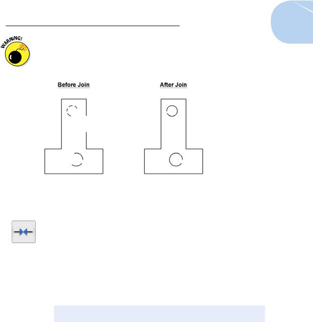
Use the JOIN command to fill gaps in lines, arcs, elliptical arcs, splines, and polylines. If the lines are collinear (that is, they lie in the same straight line), or the arcs, splines, polylines, or elliptical arcs are on a similarly curved path, JOIN will create a single new entity to replace the existing separate pieces, as shown in Figure 11-10.
www.it-ebooks.info
Chapter 11: Edit for Credit 239
Objects to be joined must be collinear or their ends must be coincident. You can’t JOIN noncollinear objects that have gaps between them or that cross or overlap.
Figure 11-10: Joining sundered pieces.
The following steps describe how to use the JOIN command:
1.Click the Modify panel title at the bottom edge of the Ribbon’s Home tab to open the Modify panel’s slideout, and then click the Join button.
If you foresee doing a lot of joinery, you can pin the slideout open, as shown in Figure 11-10. AutoCAD prompts you to select the source object.
2.Select the source object — that is, the object you want to join other objects to.
AutoCAD prompts according to the object type selected. If you select a line, the command prompt or Dynamic Input tooltip shows
Select source object or multiple objects to join at once:
3.Select valid objects to join to the original source object.
For example, if you selected a line as your source object, AutoCAD continues prompting for additional adjoining lines until you press Enter to end object selection.
4.Press Enter to end the command.
AutoCAD joins the selected objects into a single object. The new object will inherit relevant properties such as the layer or linetype of the source object.
www.it-ebooks.info

240 Part II: Let There Be Lines
Polishing those properties
When you think of editing objects, you probably think first about editing their geometry: moving, stretching, making new copies, and so on. That’s the kind of editing we cover in this chapter.
Another kind of editing is changing objects’ properties. As we describe in Chapter 6, every object in an AutoCAD drawing has a set of nongeometrical properties, including layer, color, linetype, lineweight, transparency, and maybe plot style. Sometimes you need to edit those properties — when you accidentally draw something on the wrong layer, for example. Here’s a handful of ways of editing an object’s properties in AutoCAD:
The Properties palette: This is the most flexible way to edit properties. Select any object (or objects), right-click in the drawing area, and choose Properties from the menu. The Properties palette displays the names and values of all properties. Click in the appropriate value cell to change a particular property.
The Quick Properties palette: If Quick Properties is enabled by clicking its status bar button, a palette pops up near the crosshairs when you select an object. Like the Properties palette, the Quick Properties palette contains value cells that you can click to change the specific property. You can choose how many lines of information you want Quick Properties to display by right-clicking the Quick Properties status bar button and choosing Settings.
Layers and Properties control lists: Another way to change properties is to select objects and then choose from the drop-down lists (Layer, Color, and so on) on the Properties palette. It’s fine to change layers this way, but don’t be slapdash about changing the other properties — see Chapter 6 for more information.
Match Properties: You can use Match Properties to copy the properties from a source object to one or more other objects. You can find the Match Properties button on the Clipboard panel of the Ribbon’s Home tab. Match Properties works similarly to the Format Painter button in Microsoft applications. Match Properties works even when the objects reside in different drawings.
As discussed in Chapter 6, it’s almost never correct to set the color, linetype, or lineweight to be anything other than ByLayer. To do so invites chaos.
Change Space: We introduce the concepts of model space and paper space in Chapters 4 and 5. Sometimes you add some geometry to paper space and then realize it should have been in model space, or vice versa. The CHSPACE command can come to the rescue — you’ll find it on the Modify panel slideout on the Ribbon’s Home tab. For more information, look up CHSPACE in the Command Reference of the online help.
You aren’t limited to selecting a single object at the first prompt. If you select multiple objects by using windowing, JOIN will join whatever objects it can and reject those that it can’t.
You can turn an arc into a circle or an elliptical arc into a full ellipse with JOIN’s cLose option.
www.it-ebooks.info