


Channel Handshake
3.2Relationships between the channels
The relationship between the address, read, write, and write response channels is flexible.
For example, the write data can appear at an interface before the write address that relates to it. This can occur when the write address channel contains more register stages than the write data channel. It is also possible for the write data to appear in the same cycle as the address.
When the interconnect must determine the destination address space or slave space, it must realign the address and write data. This is required to assure that the write data is signaled as valid only to the slave for which it is destined.
Two relationships that must be maintained are:
•read data must always follow the address to which the data relates
•a write response must always follow the last write transfer in the write transaction to which the write response relates.
3-6 |
Copyright © 2003, 2004 ARM Limited. All rights reserved. |
ARM IHI 0022B |
Channel Handshake
3.3Dependencies between channel handshake signals
To prevent a deadlock situation, you must observe the dependencies that exist between the handshake signals.
In any transaction:
•the VALID signal of one AXI component must not be dependent on the READY signal of the other component in the transaction
•the READY signal can wait for assertion of the VALID signal.
Note
While it is acceptable to wait for VALID to be asserted before asserting READY, it is also acceptable to assert READY by default prior to the assertion of VALID and this can result in a more efficient design.
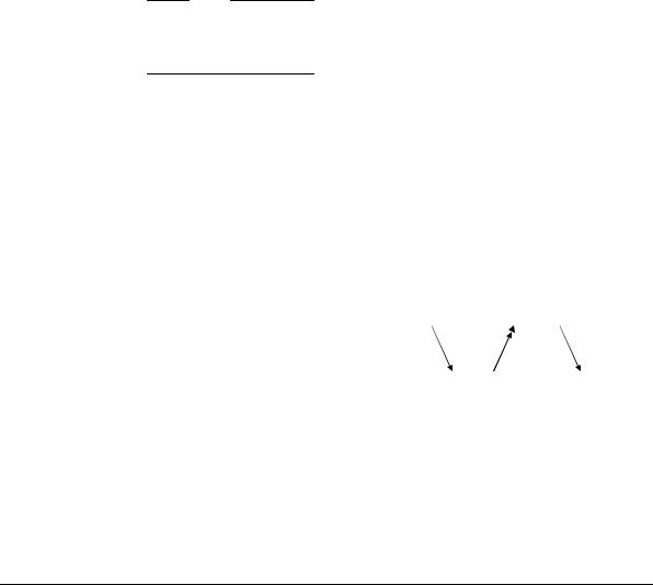
Figure 3-4 and Figure 3-5 on page 3-8 show the handshake signal dependencies. The single-headed arrows point to signals that can be asserted before or after the previous signal is asserted. Double-headed arrows point to signals that must be asserted only after assertion of the previous signal.
Figure 3-4 shows that, in a read transaction:
•the slave can wait for ARVALID to be asserted before it asserts ARREADY
•the slave must wait for both ARVALID and ARREADY to be asserted before it starts to return read data by asserting RVALID.
ARVALID  RVALID
ARREADY |
RREADY |
Figure 3-4 Read transaction handshake dependencies
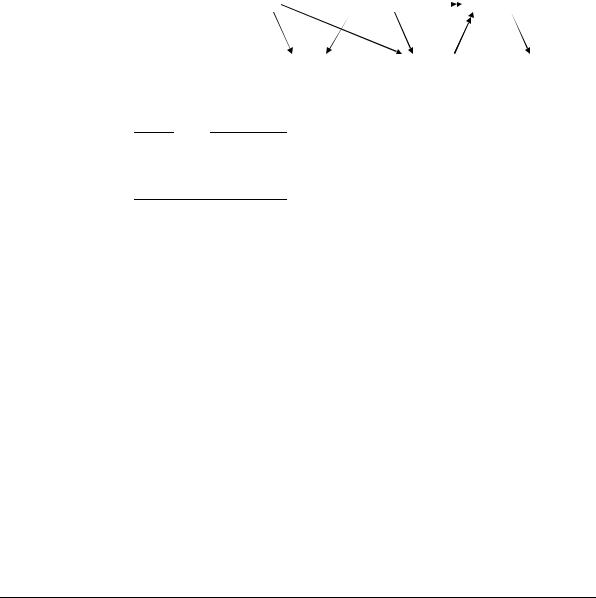
Figure 3-5 on page 3-8 shows that, in a write transaction:
•the master must not wait for the slave to assert AWREADY or WREADY before asserting AWVALID or WVALID
•the slave can wait for AWVALID or WVALID, or both, before asserting
AWREADY
ARM IHI 0022B |
Copyright © 2003, 2004 ARM Limited. All rights reserved. |
3-7 |
Channel Handshake
•the slave can wait for AWVALID or WVALID, or both, before asserting
WREADY
•the slave must wait for both WVALID and WREADY to be asserted before asserting BVALID.
AWVALID |
WVALID |
|
BVALID |
|
|||
AWREADY |
|
WREADY |
BREADY |
Figure 3-5 Write transaction handshake dependencies
Note
It is important that during a write transaction, a master must not wait for AWREADY to be asserted before driving WVALID. This could cause a deadlock condition if the slave is conversely waiting for WVALID before asserting AWREADY.
3-8 |
Copyright © 2003, 2004 ARM Limited. All rights reserved. |
ARM IHI 0022B |