

EMISSION CONTROL INFORMATION 11-1
EMISSION CONTROL INFORMATION
CONTENTS
EMISSION CONTROL SYSTEMS............................................................... |
|
|
11- 2 |
|
FUEL INJECTION SYSTEM.................................................................. |
|
|
11- 2 |
|
CRANKCASE EMISSION CONTROL SYSTEM |
................................... |
11- 3 |
||
EXHAUST EMISSION CONTROL SYSTEM (PAIR SYSTEM)............. |
11- 4 |
|||
NOISE EMISSION CONTROL SYSTEM............................................... |
|
|
11- 5 |
|
PAIR (AIR SUPPLY) SYSTEM AND |
|
|
|
|
EMISSION CONTROL SYSTEM INSPECTION .......................................... |
|
11- 6 |
||
PAIR HOSES......................................................................................... |
|
|
11- 6 |
|
PAIR REED VALVE .............................................................................. |
|
|
11- 6 |
|
PCV HOSE ............................................................................................ |
|
|
11- 6 |
|
PAIR CONTROL SOLENOID VALVE................................................... |
|
E |
11- 7 |
|
PAIR (AIR SUPPLY) SYSTEM HOSE ROUTING |
11- 8 |
|||
|
||||
HO2 SENSOR INSPECTION (For E-02, 19) ............................................... |
L |
11- 9 |
||
|
|
|||
P |
|
|
||
M |
|
|
|
|
A |
|
|
|
|
S |
|
|
|
|
11

11-2 EMISSION CONTROL INFORMATION
EMISSION CONTROL SYSTEMS
FUEL INJECTION SYSTEM
GSX-R600 motocycles are equipped with a fuel injection system for emission level control. This fuel injection system is precision designed, manufactured and adjusted to comply with the applicable emission limits. With a view to reducing CO, NOX and HC, all of the fuel injection volumes are stringently controlled with the programmed injection maps in the ECM by varying engine conditions. Adjusting, interfering with, improper replacement, or resetting of any of the fuel injection components may adversely affect injection performance and cause the motorcycle to exceed the exhaust emission level limits. if unable to effect repairs, contact the distributor’s representative for further technical informaiton and assistance.
E |
L |
P |
M |
A |
S |
1 |
Fuel tank |
7 |
Fuel feed hose |
|
|
|
|
2 |
Fuel filter (For high pressure) |
8 |
Fuel mesh filter (For low pressure) |
3 |
Fuel pressure regulator |
9 |
Fuel pump |
|
|
|
|
4 |
Fuel delivery pipe |
A |
Before-pressurized fuel |
5 |
Primary fuel injector |
B |
Pressurized fuel |
|
|
|
|
6 |
Secondary fuel injector |
C |
Relieved fuel |
EMISSION CONTROL INFORMATION 11-3
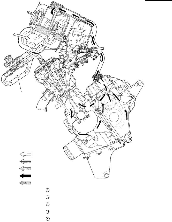
CRANKCASE EMISSION CONTROL SYSTEM
The engine is equipped with a PCV system to prevent discharging crankcase emissions into the atomosphere. Blow-by gas in the engine is constantly drawn into the crankcase, which is returned to the combustion chamber through the PCV (breather) hose, air cleaner and throttle body.
E
L
P
M
A
S
1 |
PAIR control solenoid valve |
C |
EXHAUSTGAS |
|
|
|
|
2 |
PCV hose |
D |
BLOW-BY GAS |
|
|
|
|
A |
FRESH AIR |
E |
RETURN OIL |
B |
FUEL/AIR MIXTURE |
|
|
11-4 EMISSION CONTROL INFORMATION
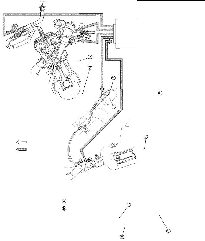
EXHAUST EMISSION CONTROL SYSTEM (PAIR SYSTEM)
The exhaust emission control system is composed of the PAIR system, exhaust control system and three-way catalyst system. The fresh air is drawn into the exhaust port through the PAIR control solenoid valve and PAIR reed valve. The PAIR control solenoid valve is operated by the ECM, and the fresh air flow is controlled according to the TPS, ECTS, IATS, IAPS and CKPS. The exhaust gas flow is performed by the exhaust control valve actuator which is controlled by the ECM by changing the exhaust control valve angle.
E |
L |
P |
M |
A |
S |
1 |
PAIR control solenoid valve |
7 |
Exhaust control valve actuator |
|
|
|
|
2 |
PAIR reed valve |
8 |
Exhaust control valve |
3 |
Air cleaner box |
9 |
Three-way catalyst |
|
|
|
|
4 |
Primary fuel injector |
0 |
HO2 sensor (For E-02, 19) |
5 |
Secondary fuel injector |
A |
FRESH AIR |
|
|
|
|
6 |
ECM |
B |
EXHAUST GAS |

EMISSION CONTROL INFORMATION 11-5
NOISE EMISSION CONTROL SYSTEM
TAMPERING WITH THE NOISE CONTROL SYSTEM PROHIBITED: Local law or federal law prohibits the following acts or the causing thereof:
1.The removal or rendering inoperative by any person, other than for purposes of maintenance, repair or replacement, of any device or element of design incorporated into any new vehicle for the purpose of noise control prior to its sale or delivery to the ultimate purchaser or while it is in use, or
2.The use of the vehicle after such device or element of design has been removed or rendered inoperative by any person.
AMONG THOSE ACTS PRESUMED TO CONSTITUTE TAMPERING ARE THE ACTS LISTED BELOW:
•Removing or puncturing the muffler, baffles, header pipes, screen type spark arrester (if equipped) or any other component which conducts exhaust gases.
•Removing or puncturing the air cleaner case, air cleaner cover, baffles or any other component which conducts intake air.
•Replacing the exhaust system or muffler with a system or muffler not marked with the same model specific code as the code listed on the Motorcycle Noise Emission Control Information label.
E
L
P
M
A
S