

ELECTRICAL SYSTEM 9-29
COMBINATION METER
DESCRIPTION
This combination meter mainly consists of the stepping motor, LCD (Liquid Crystal Display) and LED (Light Emitting Diode). This combination meter is light, thin and of high response compared to those currently in use because of this composition.
The rpm pointer is driven by the stepping motor.
The LCDs indicate Speed, Odo/Trip1/Trip2/Clock/Fuel reserve’s trip and Engine coolant temp./FI (DTC) respectively.
LED (Light Emitting Diode)
LED is used for the illumination light and each indicator light.
LED is maintenance free. LED is less electric-power consuming and stronger to vibration resistance compared to the bulb.
Engine RPM indicator light
This speedometer is equipped the engine RPM indicator light. The engine RPM indicator light is adjustable from 7 000 – 16 000 r/min. (from 7 000 r/min to 10 000 r/min, every 500 r/min and 10 000 r/min to 16 000 r/min, every 250 r/min initial setting: 13 000 r/min)
|
|
E |
|
|
|
L |
|
|
|
P |
|
|
M |
|
|
A |
|
: *1 |
|
S |
|
*4 |
*3 |
|
|
||
|
|
|
|
|
|
|
*2 |
*3 
1 |
Adjust switch (Trip/Clock/Engine revolution) |
8 |
Engine coolant temperature/FI (DTC) |
|
|
|
|
2 |
Tachometer |
9 |
Gear position indicator |
|
|
|
|
3 |
Speedometer |
*1 |
LED (Combination meter light) |
|
|
|
|
4 |
Engine RPM indicator mark |
*2 |
LCD |
|
|
|
|
5 |
Select switch |
*3 |
LED |
|
|
|
|
6 |
Odo/Trip 1/Trip 2/Clock/Fuel reserve’s trip |
*4 |
Stepping motor |
|
|
|
|
7 |
Engine RPM indicator light |
|
|
|
|
|
|
9-30 ELECTRICAL SYSTEM
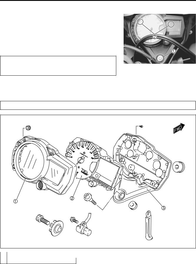
REMOVAL AND DISASSEMBLY
•Remove the screw 1.
•With the hooked parts 2 of the combination meter pulled from the headlight housing, disconnect the combination meter lead wire coupler.
•Remove the combination meter.
When disconnecting and reconnecting the combination meter coupler, make sure to turn OFF the ignition switch, or electronic parts may get damaged.
• Disassemble the combination meter as follows.
Do not attempt to disassemble the combination meter unit 2.
E |
L |
P |
M |
A |
S |
1 Combination meter cover |
3 |
Combination meter case |
2 Combination meter unit
ELECTRICAL SYSTEM 9-31
INSPECTION
LED (LIGHT EMITTING DIODE)
Check that the LED lights [FI light, Fuel level indicator light, Engine RPM indicator light and immobilizer indicator light (For E-02, 19, 24)] immediately after turning the ignition switch on. Also, other LED lights (Neutral indicator light, High-beam indicator light and Turn signal indicator light) can be checked by depending on each switch position.
If the LED fails in operation, replace the combination meter unit with a new one after checking its wire harness/coupler.
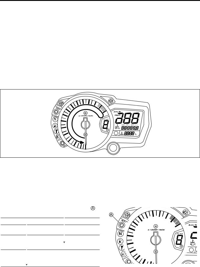
STEPPING MOTOR
Check that the pointer calibrates itself immediately after turning the ignition switch on and stops at zero point.
If abnormal condition is found, replace the combination meter unit with a new one after checking its wire harness/coupler.
|
E |
|
L |
|
P |
|
M |
NOTE: |
S |
The pointer may not return to theAproper position even turning the ignition switch on under low temperature
condition. In that case, you can reset the pointer to the proper position by following the instruction below:
1)With the adjuster switch A pressed, turn the ignition switch on.
2)Release the adjuster switch A, 3 to 5 seconds after turning the ignition switch on.
3)Press the adjuster switch A twice (within 1 second). →Reset
* Complete the operation within 10 seconds after the ignition switch has been turned on.
Time |
Ignition switch |
Adjuster switch |
|
|
|
||
|
OFF |
PUSH |
|
|
|
||
0 |
ON |
|
|
|
|
|
|
• |
|
|
|
|
|
|
|
• |
|
|
|
|
|
|
|
3 sec. |
|
|
|
|
|
|
|
• |
|
|
|
|
|
|
|
|
|
|
|
|
|
|
|
5 sec. |
|
|
Release |
|
|
|
|
• |
|
|
Push |
|
|
|
|
• |
|
|
|
|
|
||
|
|
|
|
|
|
|
|
• |
|
|
Push→Reset |
|
|
|
|
• |
|
|
|
|
|
||
|
|
|
|
|
|
|
|
10 sec. |
|
|
|
|
|
|
|
|
|
|
|
|
|
|
|
Pointer will return to the starting point right after the completion of the operation. In the case of the pointer not returning to the proper position after doing above, replace the combination meter unit.
9-32 ELECTRICAL SYSTEM
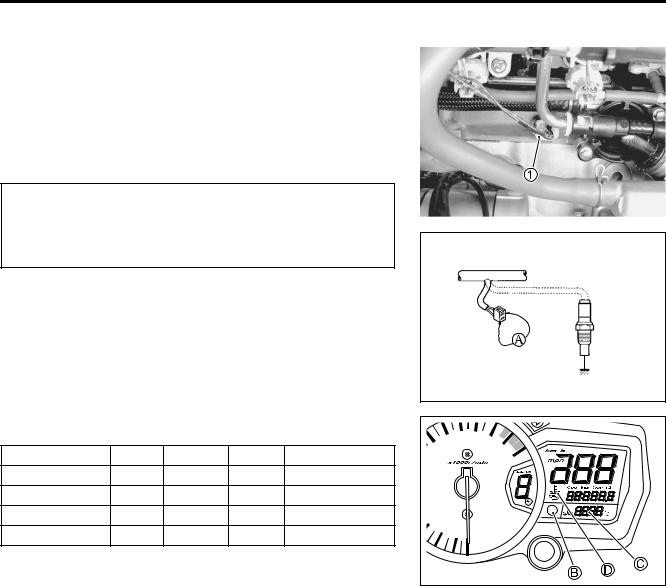
ENGINE COOLANT TEMPERATURE METER AND INDICATOR
ECT sensor inspection ( 7-7)
• Remove the front seat.( 8-7)
• Lift and support the fuel tank. ( 5-3)
• Disconnect the ECT sensor coupler 1.
|
|
|
|
|
|
When connecting and disconnecting the engine cool- |
|
||||
ant temperature sensor lead wire coupler, make sure |
|
||||
to turn OFF the ignition switch, or electronic parts |
|
||||
may get damaged. |
|
|
|
|
|
• Connect the variable resistor A between the terminals. |
|
||||
• Disconnect the oil pressure switch lead wire from the oil pres- |
|
||||
sure switch. |
|
|
|
|
|
NOTE: |
|
|
|
|
|
Leave the oil pressure switch lead wire open. |
|
|
|||
• Turn the ignition switch ON. |
|
|
E |
||
• Check the LCD and LED operations when the resistance is |
|||||
adjusted to the specified values. |
|
|
L |
||
Resistance A |
LED B LCD C LCD D Water temperature |
||||
2.45 kΩ and more |
OFF |
“---” |
------- |
19 °C and below |
|
Approx. 0.318 kΩ |
OFF |
“80” |
------- |
P |
|
Approx. 80 °C |
|
||||
0.1108 kΩ and less |
ON |
“120” – “139” |
Flicker |
120 – 139 °C |
|
0 Ω (Jumper wire) |
ON |
“HI” |
Flicker |
M |
|
140 °C and over |
|
||||
|
|
|
A |
|
|
If either one or all indications are abnormal, replace the combi- |
|
||||
nation meter with a new one. |
|
|
|
||
|
|
S |
|
|
|
NOTE:
If the engine stop switch is turned OFF or side-stand/ignition inter-lock system is not working while the ignition switch is ON, the LCD displays “CHEC”. But it is not a malfunction.
This condition implies that combination meter receives no signal from the ECM.
In that case, they are restored to normal indication by turning the engine stop switch to RUN position.
ELECTRICAL SYSTEM 9-33
FUEL LEVEL GAUGE INSPECTION
•Remove the fuel pump assembly. ( 5-9)
•Measure the resistance at each fuel level gauge float position.
If the resistance is incorrect, replace the fuel level gauge with a new one.
Float position |
Resistance |
|
|
|
|
|
|
|
|
|
|
|
|
190 mm (7.48 in) |
182 ± 3 Ω |
|
|
|
|
|
56.4 mm (2.22 in) |
4 ± 1 Ω |
|
190 mm |
|||
|
|
|
(7.48 in) |
|||
09900-25008: Multi-circuit tester set |
|
|
|
|
|
|
Tester knob indication: Resistance (Ω) |
|
|
|
56.4 mm |
||
|
|
|
|
|
(2.22 in) |
|
|
|
|
|
|
|
|
FUEL LEVEL INDICATOR LIGHT INSPECTION |
|
L |
|
If the fuel level indicator light does not function properly, check |
E |
||
the fuel level gauge and its lead wire/coupler. |
P |
|
|
|
|
|
|
If the fuel level gauge and its lead wire/coupler are functioning |
|
||
M |
|
|
|
properly, replace the combination meter with a new one. |
|
|
|
A |
|
|
|
S |
|
|
|
9-34 ELECTRICAL SYSTEM
SPEEDOMETER
If the speedometer, odometer or trip meter does not function properly, inspect the speedometer sensor and connection of couplers. If the speed sensor and connection are functioning properly, replace the meter with a new one.
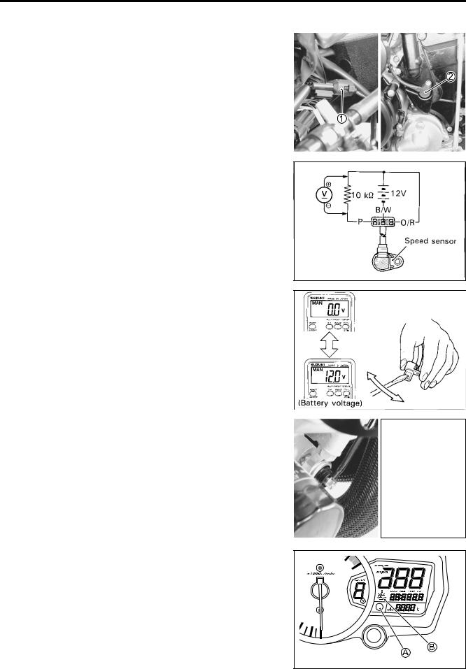
SPEED SENSOR
• Remove the front seat.( 8-7)
•Lift and support the fuel tank. ( 5-3)
•Disconnect speed sensor coupler 1.
•Remove the speed sensor 2 by removing its mounting bolt.
•Connect 12 V battery, 10 kΩ resistor and the multi-circuit
tester as shown in the right illustration.
B/R |
: Black with Red tracer |
|
|
|
|
|
|
|
10 kΩ |
|
12 V |
|
|
|||||||
|
|
|
|
|
|
|
|
|
|
|||||||||||
|
|
|
|
|
|
|
|
|
||||||||||||
B/W |
: Black with White tracer |
|
|
|
|
|
|
|
|
|
|
|
|
|
|
|
||||
|
|
|
|
|
|
|
|
|
|
B/W |
|
|
|
|
||||||
|
|
|
|
|
|
|
|
|
|
|
|
|
||||||||
|
|
|
|
|
|
|
|
|
|
|
|
|
|
|
|
|
|
|
|
|
B |
: Black |
|
|
|
|
|
|
|
|
|
B |
|
|
|
|
B/R |
|
|
||
|
|
|
|
|
|
|
|
|
|
|
||||||||||
09900-25008: Multi-circuit tester set |
|
|
|
|
|
|
|
|
|
|
|
|
|
|
|
|
||||
|
|
|
|
|
|
|
|
|
|
|
|
|
|
Speed sensor |
|
|||||
Tester knob indication: Voltage ( ) |
|
|
|
E |
|
|
|
|
|
|
|
|
||||||||
|
|
|
|
|
|
|
|
|
|
|
|
|
|
|
||||||
|
|
|
|
|
|
|
|
|
|
|
|
|
|
|
||||||
• Under above condition, if a suitable screwdriver touching the |
L |
|
|
|
|
|
|
|
|
|||||||||||
|
|
|
|
P |
|
|
|
|
|
|
|
|
||||||||
pick-up surface of the speed sensor is moved, the tester read- |
|
|
|
|
|
|
|
|
|
|
|
|
|
|
|
|
||||
ing voltage changes (0 V→ 12 V or 12 V→ 0 V). If the tester |
|
|
|
|
|
|
|
|
|
|
|
|
|
|
|
|
||||
reading voltage does not change, replace the speedometer |
|
|
|
|
|
|
|
|
|
|
|
|
|
|
|
|
||||
sensor with a new one. |
|
A |
|
|
|
|
|
|
|
|
|
|
|
|
|
|
|
|
||
|
|
|
|
|
|
|
|
|
|
|
|
|
|
|
|
|
|
|
||
NOTE: |
|
|
M |
|
|
|
|
|
|
|
|
|
|
|
|
|
|
|
|
|
The highest voltage reading in this test will be the same as that |
|
|
|
|
|
|
|
|
|
|
|
|
|
|
|
|
||||
of battery (12 V). |
S |
|
|
|
|
|
|
|
|
|
|
|
|
|
|
|
|
|
||
|
|
|
|
|
|
|
|
|
|
|
|
|
|
|
|
|
|
|
||
|
|
|
|
|
|
|
|
|
|
|
|
|
|
|
|
|
||||
|
|
|
|
|
|
|
(Battery voltage) |
|
|
|
|
|
|
|
|
|||||
|
|
|
|
|
|
|
|
|
|
|
|
|
|
|
|
|
|
|
|
|
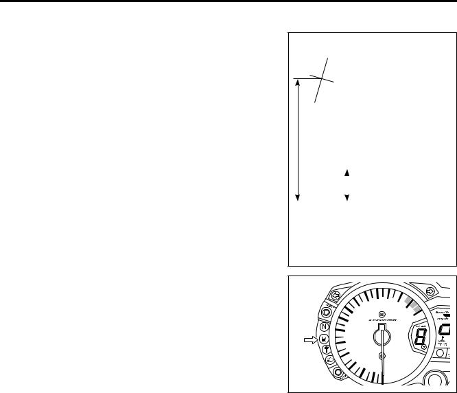
OIL PRESSURE INDICATOR
NOTE:
Before inspecting the oil pressure switch, check if the engine oil level is correct. ( 2-12)
•Remove the left under cowling. ( 8-5)
•Disconnect the oil pressure switch lead wire from the oil pressure switch.
•Turn the ignition switch ON.
•Check if the oil pressure indicator A will light and LCD B will flicker, when grounding the lead wire.
If any indications are abnormal, replace the combination meter with a new one after checking connection of couplers.