

CHASSIS 8-3
EXTERIOR PARTS
FASTENER REMOVAL AND INSTALLATION
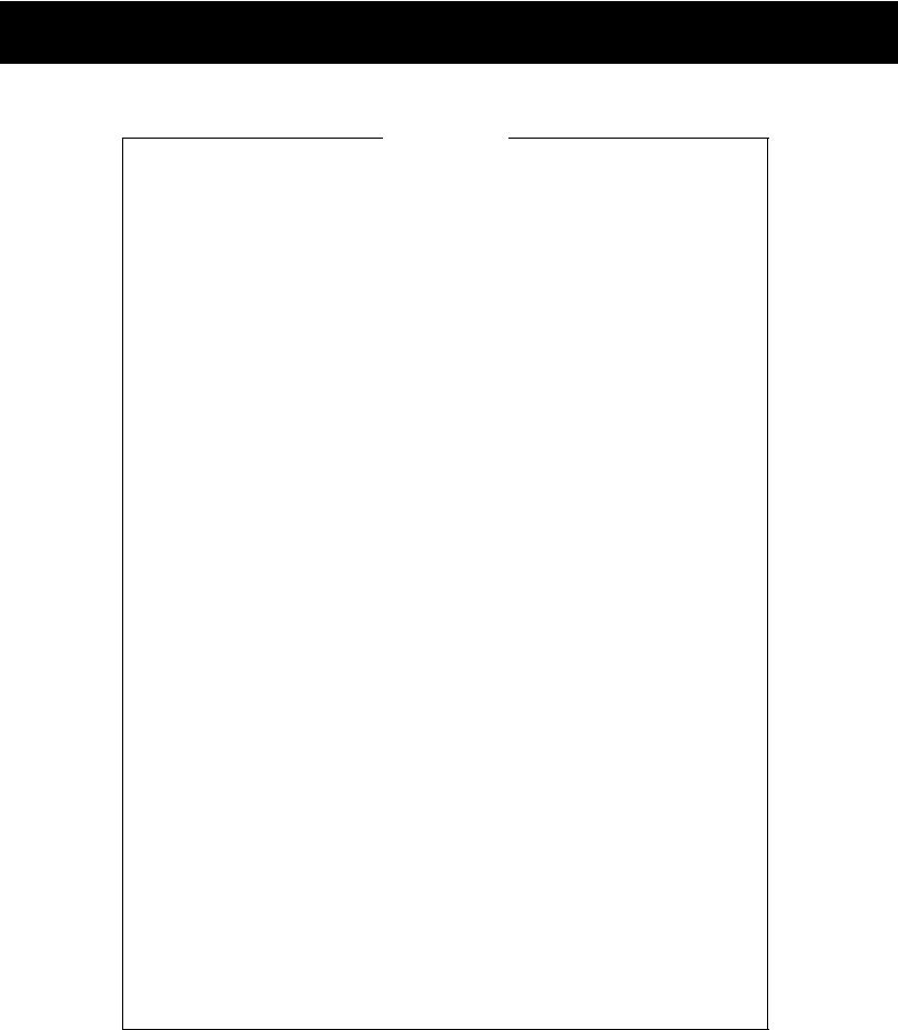
FASTENER (Type A) Removal
• Depress the head of fastener center piece 1.
• Pull out the fastener a.
Installation
• Let the center piece stick out toward the head so that the pawls 2 close.
• Insert the fastener into the installation hole.
NOTE: |
|
|
To prevent the pawl 2 from damage, insert the fastener all the |
E |
|
way into the installation hole. |
|
|
|
|
|
|
L |
|
|
P |
|
• Push in the head of center piece until it becomes flush with |
|
|
the fastener outside face. |
M |
|
|
|
|
|
A |
|
S |
|
|
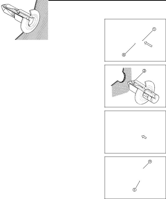
FASTENER (Type B)
Removal
•Pry up the head of fastener center piece 1 with a screw driver.
•Pull out the fastener a.
8-4 CHASSIS
Installation
• Insert the fastener into the installation hole.
NOTE:
To prevent the pawl 2 from damage, insert the fastener all the way into the installation hole.
• Push in the head of center piece.
E
L
P
M
A
S
CHASSIS 8-5
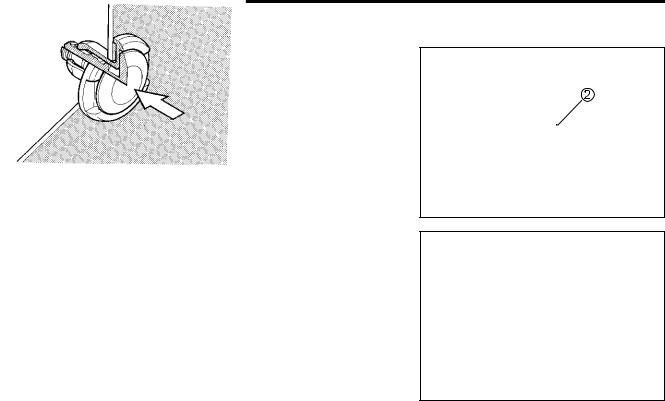
BODY COWLING COVER AND LOWER BRACKET COVER
REMOVAL
• Remove the body cowling cover 1 by removing the screws and fasteners.
• Remove the lower bracket cover 2 by removing the bolts.
INSTALLATION
•Install the lower bracket cover and body cowling cover in the reverse order of removal.
INNER UNDER COWLING
REMOVAL
•Remove the body cowling cover. ( Above)
•Remove the inner under cowlings 1. (LH/RH)
INSTALLATION
•Install the inner under cowlings in the reverse order of removal.
|
E |
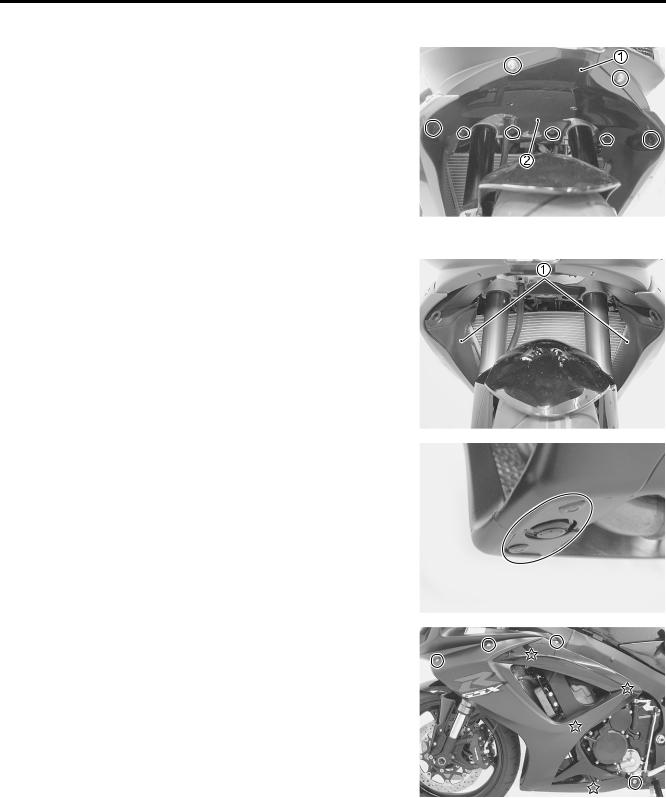
UNDER COWLING |
P |
L |
|
• Remove the body cowling cover and inner under cowlings. |
|
( Above) |
M |
• Remove the fasteners. |
A |
|
|
S |
|
• Remove the under cowlings. (LH/RH)
NOTE:
“ ” indicates hook location.
INSTALLATION
• Install the under cowlings in the reverse order of removal.
8-6 CHASSIS
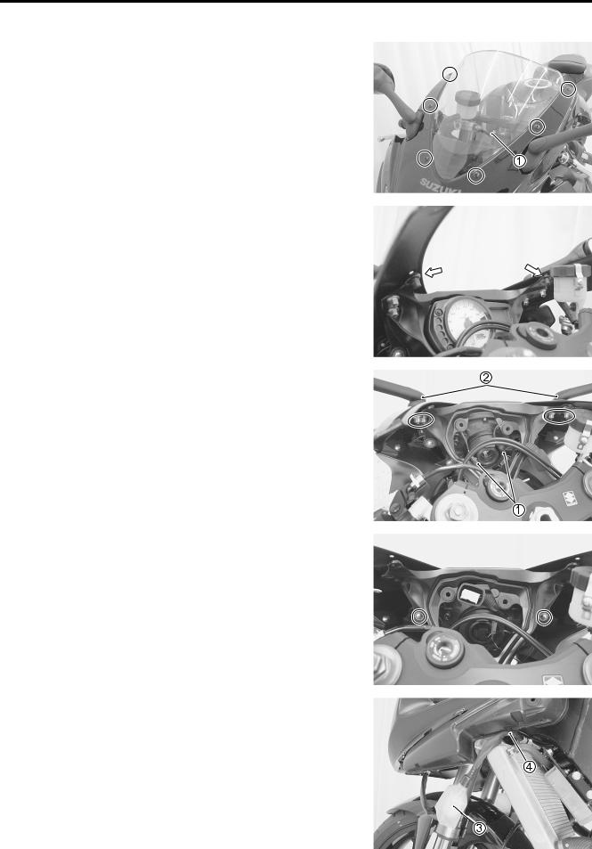
SCREEN
REMOVAL
• Remove the screen 1 by removing the screws.
INSTALLATION
•Install two nuts (middle ones) as shown.
•Install the window screen.
BODY COWLING |
|
|
L |
|
|
E |
|
REMOVAL |
|
P |
|
• Remove the left and right under cowlings. ( 8-5) |
|
|
|
• Remove the screen. ( Above) |
M |
|
|
|
|
|
|
• Remove the combination meter. ( 9- |
) |
|
|
A |
|
|
|
• Disconnect the turn signal lead wire couplers 1. |
|
|
|
• Remove the rear view mirror/turn signal assemblies 2. |
|
||
S |
|
|
|
• Remove the screws.
•Disconnect the lead wire coupler 3 and remove wire clamp
4.
•Remove the body cowling.
INSTALLATION
• |
Install the body cowling in the reverse order of removal. |
• |
Refer to the turn signal cable routing. ( 10- ) |
CHASSIS 8-7
AIR INTAKE PIPE
REMOVAL
• Remove the body cowling. ( 8-6)
• Remove the fasteners.
• Remove the air intake pipes 1. (LH/RH)
INSTALLATION
• Install the air intake pipes in the reverse order of removal.
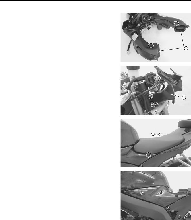
COWLING BRACE
REMOVAL
•Remove the body cowling. ( 8-6)
•Remove the cowling brace 1.
INSTALLATION
• Install the cowling brace in the reverse order of removal.
• Tighten the cowling brace bolts.
Cowling brace bolt: 23 N·m (2.3 kgf-m, 16.5 lb-ft)
|
|
|
L |
FRONT SEAT |
|
|
E |
REMOVAL |
|
|
|
• Remove the front seat by removing the bolts. |
|
|
|
|
M |
|
|
INSTALLATION |
|
P |
|
• Install the front seat in the reverse order of removal. |
|
||
|
A |
|
|
|
S |
|
|
FUEL TANK LOWER SIDE COVER
REMOVAL
•Remove the front seat. ( Above)
•Remove the fuel tank lower side covers 1. (LH/RH)
NOTE:
“ ” indicates hook location.
INSTALLATION
•Install the fuel tank lower side covers in the reverse order of removal.
8-8 CHASSIS
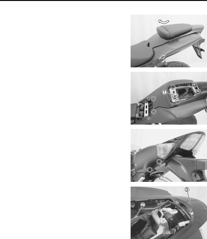
REAR SEAT/SEAT TAIL COVER
REMOVAL
• Remove the rear seat (seat tail cover) using the ignition key.
INSTALLATION
•Insert the seat hook to the guide and push down the seat (seat tail cover) firmly until the seat (seat tail cover) snaps into the locked position.
FRAME COVER
REMOVAL
• Remove the front and rear seats. ( 8-7 and -8)
• Remove the fasteners and screws.
• Disconnect the seat lock cable 1.
E
L
P
M
A
S
•Disconnect the rear combination light lead wire coupler 2.
•Remove the frame cover 3.
NOTE:
“ ” indicates hook location.
INSTALLATION
Install the frame cover in the reverse order of removal.