


|
|
|
|
|
CHASSIS 8-75 |
|
REAR BRAKE |
|
|
|
|
|
|
CONSTRUCTION |
|
|
|
|
|
|
|
|
E |
|
|
|
|
|
|
L |
|
|
|
|
|
|
P |
|
|
|
|
|
|
M |
|
|
|
|
|
|
A |
|
|
|
|
|
S |
|
|
|
|
|
1 |
Brake pedal |
A Caliper air bleeder valve |
|
|
|
|
2 |
Piston/Cup set |
B Brake hose union bolt |
ITEM |
N·m kgf-m lb-ft |
||
3 |
Reservoir hose |
C Brake caliper mounting bolt |
A |
7.5 |
0.75 |
5.5 |
4 |
Brake hose |
D Brake master cylinder mounting bolt |
B |
23 |
2.3 |
16.5 |
5 |
Brake pad |
E Brake master cylinder rod lock-nut |
C |
17 |
1.7 |
12.5 |
6 |
Piston |
F Brake pad mounting pin |
D |
10 |
1.0 |
7.0 |
7 |
Brake pad spring |
G Brake caliper pin bolt |
E |
18 |
1.8 |
13.0 |
|
|
|
F |
15 |
1.5 |
11.0 |
|
|
|
G |
32 |
3.2 |
23.0 |
8-76 CHASSIS
*This brake system is filled with an ethylene glycol-based DOT 4 brake fluid. Do not use mix different types of fluid such as silicone-based or petroleum-based.
*Do not use any brake fluid taken from old, used or unsealed containers. Never reuse brake fluid left over from the last servicing or stored for long periods.
*When storing the brake fluid, seal the container completely and keep away from children.
*When replenishing brake fluid, take care not to get dust into fluid.
*When washing brake components, use fresh brake fluid. Never use cleaning solvent.
*A contaminated brake disc or brake pad reduces braking performance. Discard contaminated pads and clean the disc with high quality brake cleaner or neutral detergent.
Handle brake fluid with care: The fluid reacts chemically with paint, plastics, rubber materials etc. and will damage then severely.
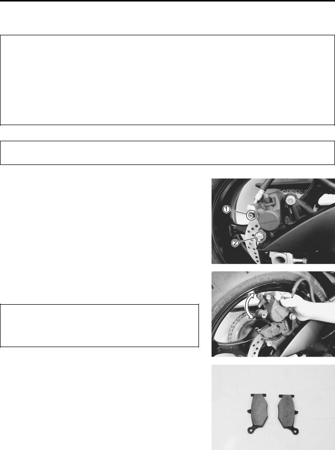
BRAKE PAD REPLACEMENT
• Remove the pad mounting pin 1. |
E |
|
• Remove the caliper mounting bolt 2. |
||
|
|
|
|
|
L |
|
P |
|
|
M |
|
• Remove the brake pads with the rear caliper pivoted up. |
|
|
|
A |
|
• Clean up the caliper especially around the caliper piston. |
|
|
|
S |
|
|
|
|
*Do not operate the brake pedal with the pads removed.
*Replace the brake pads as a set, otherwise braking performance will be adversely affected.
•Install the new brake pads.
Pad mounting pin: 15 N·m (1.5 kgf-m, 11.0 lb-ft)
Brake caliper mounting bolt: 17 N·m (1.7 kgf-m, 12.5 lb-ft)
NOTE:
After replacing the brake pads, pump the brake pedal a few times to set the brake parts correctly and then check the brake fluid level.

CHASSIS 8-77
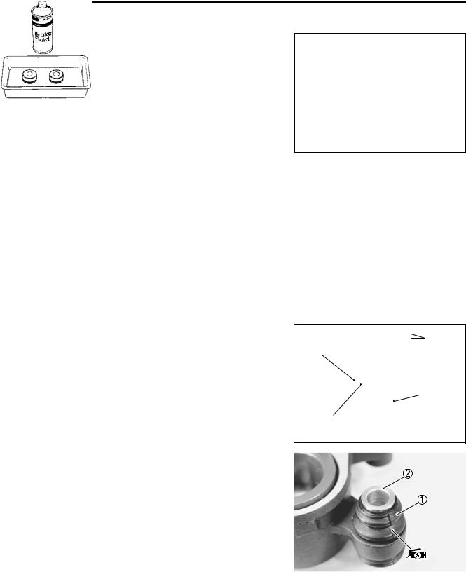
BRAKE FLUID REPLACEMENT
• Remove the brake fluid reservoir mounting bolt 1.
• Place a rag underneath the brake fluid reservoir to catch any split brake fluid. Remove the brake fluid reservoir cap 2.
•Replace the brake fluid in the same manner as the front brake. ( 8-66)
Specification and classification: DOT 4
Bleed air from the brake system. ( 2-23)
|
|
E |
|
|
L |
|
|
P |
CALIPER REMOVAL AND DISASSEMBLY |
||
• Drain the brake fluid. |
M |
|
|
|
A |
• Remove the brake hose from the caliper by removing the |
||
union bolt 1 and catch the brake fluid in a suitable recepta- |
||
cle. |
S |
|
|
|
|
NOTE:
Place a rag underneath the union bolt on the brake caliper to catch any split brake fluid.
•Remove the pad mounting pin 2.
•Remove the caliper mounting bolt 3.
•Remove the brake caliper.
Never reuse the brake fluid left over from previous servicing and stored for long periods.
Brake fluid, if it leaks, will interfere with safe running and discolor painted surfaces. Check the brake hose and hose joints for cracks and fluid leakage.
8-78 CHASSIS
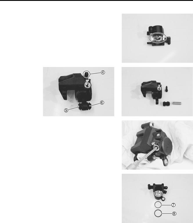
•Remove the brake pad spring.
•Remove the caliper air bleeder valve 4.
•Remove the spacer 5 and rubber boot 6 from the caliper.
|
|
|
|
E |
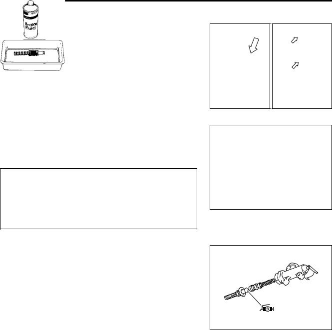
• Place a rag over the piston to prevent it from popping out and |
L |
|||
then force out the pistons using compressed air. |
P |
|||
|
|
|
||
|
|
|
|
|
|
|
|
|
|
|
M |
|
|
|
Avoid using high pressure air to prevent piston dam- |
|
|
||
age. |
A |
|
|
|
|
|
|
|
|
|
S |
|
|
|
• Remove the dust seal 7 and piston seal 8. |
|
|
|
|
|
|
|
|
|
|
|
|||
Avoid reusing the dust seals and piston seals to pre- |
|
|
||
vent fluid leakage. |
|
|
|
|
|
|
|
|
|
CHASSIS 8-79
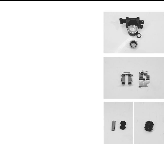
CALIPER INSPECTION
BRAKE CALIPER AND BRAKE CALIPER PISTON
•Inspect the brake caliper cylinder wall for nicks, scratches and other damage. If any damage is found, replace the caliper with a new one.
•Inspect the brake caliper piston surface for any scratches and other damage. If any damage is found, replace the caliper with a new one.
BRAKE PAD SPRING BOOTS AND SPACER
•Inspect the brake pad spring for damage and excessive bend. If any damage is found, replace the brake pad spring with a new one.
•Inspect the boots and spacer for damage and wear. If any damage is found, replace boot and spacer with new ones.
E
L
P
M
A
S
BRAKE DISC INSPECTION
•Inspect the rear brake disc in the same manner as the front brake disc. ( 8-70)
Service Limit
Rear disc thickness: 4.5 mm (0.18 in) Rear disc runout: 0.30 mm (0.012 in)
CHASSIS 8-81
CALIPER INSTALLATION
Install the caliper in the reverse order of removal. Pay attention to the following points:
• Tighten each bolt to the specified torque.
Brake hose union bolt 1: 23 N·m (2.3 kgf-m, 16.5 lb-ft) Brake caliper mounting bolt 2:
17 N·m (1.7 kgf-m, 12.5 lb-ft) Brake caliper pin bolt 3: 32 N·m (3.2 kgf-m, 23.0 lb-ft)
2-20)
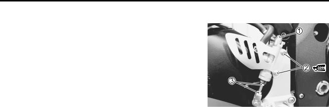
MASTER CYLINDER REMOVAL AND
DISASSEMBLY
• Remove the brake fluid reservoir mounting bolt 1. |
|
E |
|
• Place a rag underneath the brake fluid reservoir to catch any |
|||
split brake fluid. Remove the brake fluid reservoir cap 2. |
|
||
• Drain the brake fluid. |
|
L |
|
P |
|
||
|
|
||
|
M |
|
|
• Place a rag underneath the union bolt on the master cylinder |
|
||
|
A |
|
|
to catch spilled drops of brake fluid. Remove the union bolt 3 |
|
||
and disconnect the Sbrake hose. |
|
|
|
• Loosen the lock-nut 4.
• Remove the mounting bolts 5.
Immediately and completely wipe off any brake fluid contacting any parts of the motorcycle. The fluid reacts chemically with paint, plastic and rubber materials, etc. and will damage them severely.
•Disconnect the reservoir hose.
•Remove the master cylinder by turning the master cylinder rod 6.

8-82 CHASSIS
•Remove the reservoir cap 7, insulator 8, diaphragm 9 and reservoir tank 0.
• Remove the snap ring A with the special tool.
09900-06108: Snap ring pliers
• Remove the connector B. |
|
E |
|
L |
|
• Remove the O-ring C. |
|
|
|
P |
|
|
|
|
|
|
|
Replace the O-ring with a new one. |
M |
|
|
|
|
|
|
|
A |
|
|
S |
|
|
• Pull out the dust boot D, then remove the snap ring E.
09900-06108: Snap ring pliers
• Remove the following parts.
F Push rod
G Secondary cup H Piston
I Primary cup J Return spring
CHASSIS 8-83
MASTER CYLINDER INSPECTION
CYLINDER, PISTON AND CUP SET
•Inspect the cylinder bore wall for any scratches or other damage.
• Inspect the cup set and each rubber part for damage.
MASTER CYLINDER REASSEMBLY
Reassemble the master cylinder in the reverse order of disassembly. Pay attention to the following points:
* Clean the master cylinder components with fresh |
|
|
brake fluid before reassembly. Never use cleaning |
E |
|
solvent or gasoline to clean them. |
|
|
|
|
|
* Do not wipe the components with a rag. |
L |
|
|
||
* Apply brake fluid to the cylinder bore and all the |
|
|
component to be inserted into the bore. |
P |
|
|
|
|
Specification and classification: DOT 4 |
|
|
• Apply SUZUKI SILICONE GREASE to the push rod end. |
|
|
A |
|
|
99000-25100: SUZUKI SILICONEMGREASE |
|
|
S |
|
|
8-84 CHASSIS
MASTER CYLINDER INSTALLATION
Install the master cylinder in the reverse order of removal. Pay attention to the following points:
• Apply THREAD LOCK to the master cylinder mounting bolts.
99000-32110: THREAD LOCK SUPER “1322”
(or equivalent thread lock)
• Tighten each bolt to the specified torque. (Brake hose routing: 10-25)
Brake hose union bolt 1: 23 N·m (2.3 kgf-m, 16.5 lb-ft) Master cylinder mounting bolt 2:
10 N·m (1.0 kgf-m, 7.0 lb-ft) Master cylinder rod lock-nut 3:
18 N·m (1.8 kgf-m, 13.0 lb-ft)
* The seal washers should be replaced with the new |
|
||
ones to prevent fluid leakage. |
|
E |
|
* Bleed air from the system after reassembling the |
|||
|
|||
master cylinder. ( 2-23) |
|
L |
|
|
|
||
|
|
||
• Adjust the brake pedal height. ( 2-25) |
P |
||
|
M |
|
|
A |
|
||
S |
|
|
|