

COOLING AND LUBRICATION SYSTEM 7-11
WATER PUMP
REMOVAL AND DISASSEMBLY
NOTE:
Before draining engine oil and engine coolant, inspect engine oil and coolant leakage between the water pump and crankcase. If engine oil is leaking, visually inspect the oil seal and O-ring. If engine coolant is leaking, visually inspect the mechanical seal and seal washer. ( 7-13)
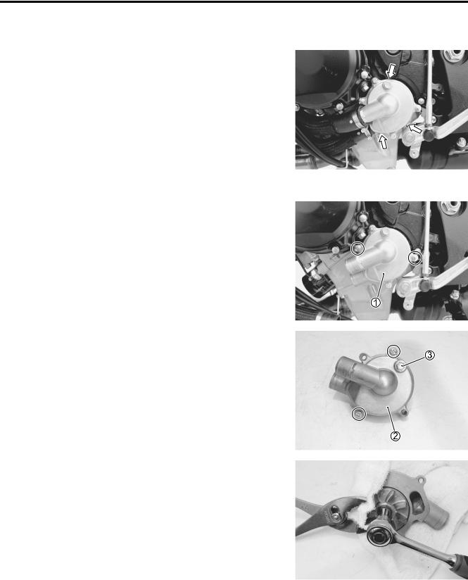
•Remove the under cowlings. ( 8-5)
•Drain the engine coolant. ( 2-17)
•Drain the engine oil. ( 2-12)
•Remove the water pump assembly 1.
E |
L |
• Remove the water pump cover 2 and air bleeder plug 3. |
P |
M |
A |
S |
•Remove the impeller securing bolt by holding the impeller with a pliers.
7-12 COOLING AND LUBRICATION SYSTEM
•Remove the mechanical seal ring 4 and rubber seal 5 from the impeller.
• Remove the impeller shaft 6 and washer 7.
|
|
|
|
E |
||
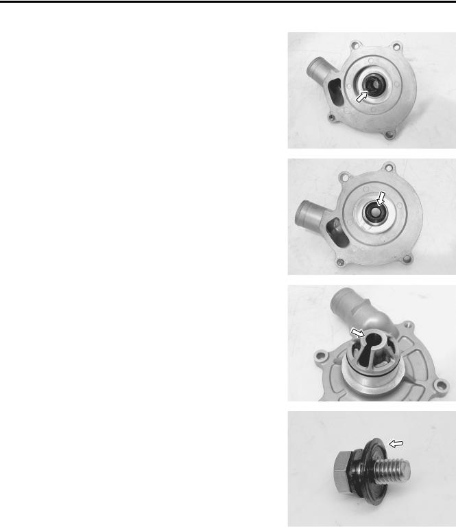
• Remove the mechanical seal with the special tool. |
|
|
L |
|||
09921-20240: Bearing remover set (12 mm) |
P |
|||||
|
|
|
|
|
||
|
|
|
|
|
||
NOTE: |
M |
|
|
|
||
|
|
|
|
|||
If there is no abnormal condition, the mechanical seal removal is |
|
|
|
|||
not necessary. |
A |
|
|
|
|
|
|
|
|
|
|
|
|
|
|
|
|
|
|
|
|
|
|
|
|
|
|
|
S |
|
|
|
|
|
The removed mechanical seal must be replaced with a |
|
|
|
|
||
new one. |
|
|
|
|
|
|
• Remove the oil seal using a suitable bar.
NOTE:
If there is no abnormal condition, the oil seal removal is not necessary.
The removed oil seal must be replaced with a new one.
COOLING AND LUBRICATION SYSTEM 7-13
INSPECTION
MECHANICAL SEAL
•Visually inspect the mechanical seal for damage, with particular attention given to the sealing face.
•Replace the mechanical seal that shows indications of leakage. Also replace the seal ring if necessary.
OIL SEAL
•Visually inspect the oil seal for damage, with particular attention given to the lip.
•Replace the oil seal that shows indications of leakage.
|
|
E |
IMPELLER SHAFT JOURNAL |
|
L |
|
|
|
• Visually inspect the journal for damage or scratch. |
|
|
• Replace the water pump body if necessary. |
P |
|
M |
|
|
A |
|
|
S |
|
|
SEAL WASHER
•Visually inspect the seal washer for damage, with particular attention given to the sealing face.
•Replace the seal washer that shows indications of leakage.
7-14 COOLING AND LUBRICATION SYSTEM
REASSEMBLY AND INSTALLATION
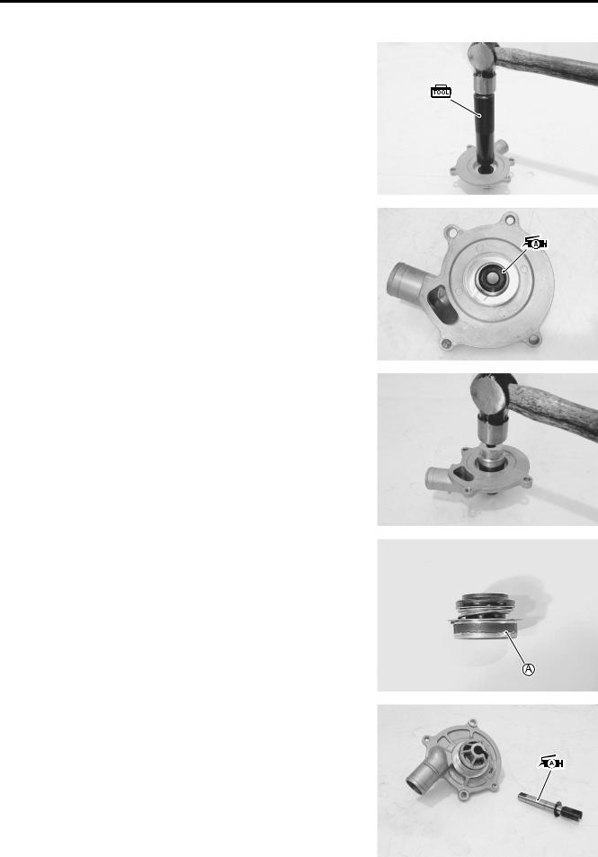
• Install the oil seal with the special tool.
09913-70210: Bearing installer set ( 22)
NOTE:
The stamped mark on the oil seal faces mechanical seal side.
•Apply a small quantity of the SUZUKI SUPER GREASE “A” to the oil seal lip.
99000-25010: SUZUKI SUPER GREASE “A”
(or equivalent grease)
|
|
E |
• Install the new mechanical seal using a suitable size socket |
L |
|
wrench. |
P |
|
|
|
|
|
M |
|
|
A |
|
|
S |
|
NOTE:
On the new mechanical seal, the sealer A has been applied.
• Apply SUZUKI SUPER GREASE “A” to the impeller shaft.
99000-25010: SUZUKI SUPER GREASE “A”
(or equivalent grease)
• Install the impeller shaft to the water pump body.

COOLING AND LUBRICATION SYSTEM 7-15
•Install the rubber seal 1 into the impeller.
•After wiping off the oily or greasy matter from the mechanical seal ring, install it into the impeller.
NOTE:
The paint marked side B of mechanical seal ring faces the rubber seal.
• Install the washer 2 and seal washer 3 onto the impeller securing bolt 4.
NOTE:
The metal side C of seal washer and the curved side D of washer face the impeller securing bolt head.
|
|
|
E |
|
|
L |
|
• Install the impeller 5 and its securing bolt onto the shaft. |
|
||
|
P |
|
|
• Tighten the impeller securing bolt to the specified torque. |
|
||
Impeller securing bolt: 8 N·m (0.8 kgf-m, 6.0 lb-ft) |
|
|
|
NOTE: |
M |
|
|
|
|
|
|
Before installing the impeller securing bolt, apply a small quan- |
|
||
tity of the THREAD LOCK to it. |
|
|
|
S |
|
|
|
99000-32050: THREADALOCK “1342” |
|
|
|
• Install the new O-rings 6 and 7.
Use the new O-rings to prevent engine coolant leakage.
NOTE:
*Apply engine coolant to the O-ring 6.
*Apply SUZUKI SUPER GREASE “A” to the O-ring 7.
99000-25010: SUZUKI SUPER GREASE “A”
(or equivalent grease)
• Tighten the water pump cover screws to the specified torque.
Water pump cover screw: 5 N·m (0.5 kgf-m, 3.5 lb-ft)
• Tighten the air bleeder plug securely.
7-16 COOLING AND LUBRICATION SYSTEM
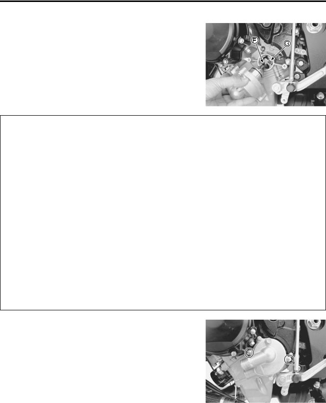
• Install the water pump.
NOTE:
Set the water pump shaft end F to the oil pump shaft G as shown.
E
L
P
M
A
S
•Tighten the water pump mounting bolts to the specified torque.
Water pump mounting bolt: 10 N·m (1.0 kgf-m, 7.0 lb-ft)
•Connect the water hoses. ( 10-24)
•Pour engine coolant. ( 2-17)
•Pour engine oil. ( 2-13)
•Install the under cowlings. ( 8-5)