

CHASSIS 8-85
TIRE AND WHEEL
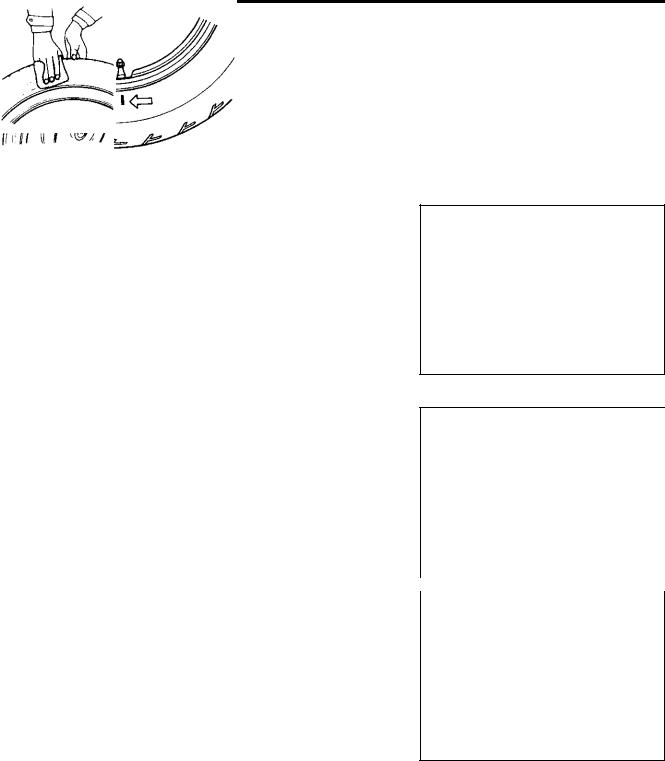
TIRE REMOVAL
The most critical factor of tubeless tire is the seal between the wheel rim and the tire bead. For this reason, it is recommended to use a tire changer that can satisfy this sealing requirement and can make the operation efficient as well as functional.
For operating procedures, refer to the instructions supplied by the tire changer manufacturer.
NOTE:
When removing the tire in the case of repair or inspection, mark the tire with a chalk to indicate the tire position relative to the valve position.
Even though the tire is refitted to the original position after repairing puncture, the tire may have to be balanced again since such a repair can cause imbalance.
INSPECTION |
|
P |
E |
|
|
|
|
||||
|
|
|
|||
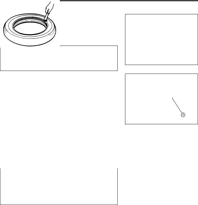
WHEEL |
|
|
|
||
|
|
|
|
||
Wipe the wheel clean and check for the following: |
|
L |
|
||
• Distortion and crack |
M |
|
|
|
|
|
|
|
|
||
• Any flaws and scratches at the bead seating area. |
|
|
|
||
• Wheel rim runout ( 8-12) |
|
|
|
|
|
A |
|
|
|
|
|
S |
|
|
|
|
|
|
|
|
|
|
|
|
|
|
|
|
|
TIRE |
|
|
|
|
|
Tire must be checked for the following points: |
|
|
|
|
|
•Nick and rupture on side wall
•Tire tread depth ( 2-27)
•Tread separation
•Abnormal, uneven wear on tread
•Surface damage on bead
•Localized tread wear due to skidding (Flat spot)
•Abnormal condition of inner liner
8-86 CHASSIS
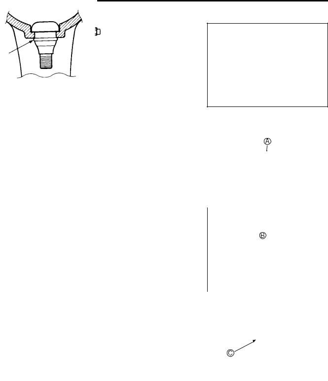
VALVE INSPECTION
•Inspect the valve after the tire is removed from the rim.
•Replace the valve with a new one if the seal A rubber is peeling or has damage.
NOTE:
If the external appearance of the valve shows no abnormal condition, removing of the valve is not necessary.
If the seal has abnormal deformation, replace the valve with a new one.
|
|
|
|
|
|
|
|
|
|
|
|
• Any dust or rust around the valve hole B must be cleaned off. |
L |
||||
|
E |
||||
• Then install the valve C in the rim. |
P |
||||
|
|
|
|
||
NOTE: |
|
M |
|
|
|
|
|
|
|
||
To properly install the valve into the valve hole, apply a special |
|
|
|||
tire lubricant or neutral soapy liquid to the valve. |
|
|
|||
|
A |
|
|
||
|
|
|
|
|
|
|
|
|
|
|
|
|
S |
|
|
|
|
Be careful not to damage the lip |
C of valve. |
|
|
|
|
|
|
|
|
|
|
|
|
|
|
|
|
|
|
|
|
|
|
|
|
|
|
|
|
CHASSIS 8-87
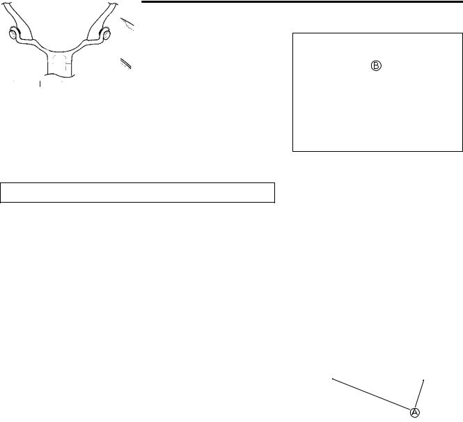
TIRE INSTALLATION
•Apply tire lubricant to the tire bead.
•When installing the tire onto the wheel, observe the following points.
*Do not reuse the valve which has been once removed.
*Never use oil, grease or gasoline on the tire bead in place of tire lubricant.
•When installing the tire, the arrow A on the side wall should point to the direction of wheel rotation.
•Align the chalk mark put on the tire at the time of removal with the valve position.
|
|
|
|
E |
|
|
L |
||
• For installation procedure of tire onto the wheel, follow the |
|
|||
|
P |
|
||
instructions given by the tire changer manufacturer. |
|
|
|
|
• Bounce the tire several times while rotating. This makes the |
|
|||
|
M |
|
|
|
tire bead expand outward to contact the wheel, thereby facili- |
|
|||
tating air inflation. |
A |
|
|
|
|
|
|
|
|
• Inflate the tire. |
S |
|
|
|
|
|
|
|
|
*Do not inflate the
can burst and possibly cause injury. Do not stand directly over the tire while inflating.
*In the case of preset pressure air inflator, pay special care for the set pressure adjustment.tire to more than 400 kPa (4.0kgf/cm², 57 psi). If inflated beyond this limit, the tire
8-88 CHASSIS
•In this condition, check the “rim line” B cast on the tire side walls. The line must be equidistant from the wheel rim all
around. If the distance between the rim line and wheel rim varies, this indicates that the bead is not properly seated. If this is the case, deflate the tire completely and unseat the bead for both sides. Coat the bead with lubricant and fit the tire again.
•When the bead has been fitted properly, adjust the pressure to specification.
•As necessary, adjust the tire balance.
Do not run with a repaired tire at a high speed.
Cold inflation tire pressure |
|
|
|
|
|
|
|
|
|
|
|
|
|
|
Front |
Rear |
|
|
|
|
|
|
|
|
|
|
|
Solo riding |
250 kPa |
250 kPa |
|
|
|
|
(2.50 kgf/cm², 36 psi) |
(2.50 kgf/cm², 36 psi) |
|
|
E |
||
|
|
|
||||
Dual riding |
250 kPa |
290 kPa |
|
|
|
|
|
|
L |
||||
(2.50 kgf/cm², 36 psi) |
(2.90 kgf/cm², 42 psi) |
|
||||
|
|
|||||
|
|
|
|
|||
|
|
|
|
|
|
|
BALANCER WEIGHT INSTALLATION |
P |
|
||||
|
||||||
|
|
M |
|
|
||
• When installing the balancer weights to the wheel, set the two |
|
|
||||
balancer weights A on both sides of wheel rim. |
|
|
|
|
||
|
A |
|
|
|
|
|
|
|
|
|
|
|
|
|
|
|
|
|
|
|
|
S |
|
|
|
|
|
Weight difference between the two balancer weights |
|
|
|
|||
must be less than 10 g (0.02 lb). |
|
|
|
|
|
|
|
|
|
|
|
|
|