

9-40 ELECTRICAL SYSTEM
BATTERY
SPECIFICATIONS
Type designation |
|
FTX9-BS |
|
|
|
|
|
|
|
|
|
|
|
Capacity |
|
12V,28.8kC (8Ah)/10 HR |
|
|
|
|
|
|
|
|
|
|
|
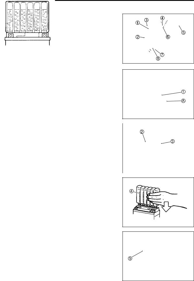
1 Upper cover breather |
5 Terminal |
|
||||
2 Cathode plates |
6 Safety valve |
|
||||
3 Stopper |
7 Anode plates |
|
|
|
||
|
|
|||||
|
||||||
4 Filter |
8 Separator (Fiberglass plate) |
|
|
|
||
|
|
|||||
INITIAL CHARGING
Filling electrolyte
• Remove the aluminum tape 1 sealing the battery electrolyte filler holes A.
NOTE: |
|
|
|
|
|
|
When filling electrolyte, the battery must be removed from the |
||||||
vehicle and must be put on the level ground. |
|
|
|
E |
|
|
• Remove the caps 2. |
|
P |
|
|
||
|
|
|
|
|||
NOTE: |
|
|
|
|||
|
|
L |
||||
* After filling the electrolyte completely, use the removed cap |
2 |
|
|
|
||
as sealing caps of battery-filler holes. |
M |
|
|
|
|
|
|
|
|
|
|
||
* Do not remove or pierce the sealed areas |
3 of the electrolyte |
|||||
container. |
A |
|
|
|
|
|
|
S |
|
|
|
|
|
|
|
|
|
|
|
|
• Insert the nozzles of the electrolyte container 4 into the battery’s electrolyte filler holes, holding the container firmly so that it does not fall. Take precaution not to allow any of the fluid to spill.
•Make sure air bubbles 5 are coming up each electrolyte container, and leave in this position for about more than 20 minutes.
ELECTRICAL SYSTEM 9-41
NOTE:
If no air bubbles are coming up from a filler port, tap the bottom of the electrolyte container two or three times.
Never remove the container from the battery.
•After confirming that the electrolyte has entered the battery completely, remove the electrolyte containers from the battery. Wait for about 20 minutes.
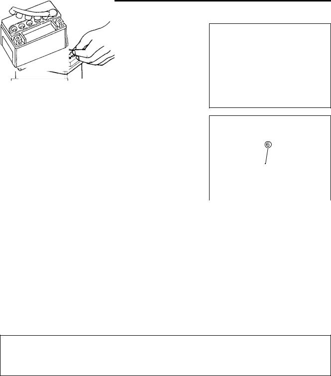
•Insert the caps 6 into the filler holes, pressing in firmly so that the top of the caps do not protrude above the upper surface of the battery’s top cover.
* Never use anything except the specified battery. |
|
|
|
|
||
* Once the caps have been installed to the battery, do |
|
|
|
|||
not remove the caps. |
|
|
E |
|
||
* Do not tap the caps with a tool such as hammer |
|
|||||
|
|
|
||||
when installing them. |
|
|
|
|
|
|
|
|
|
|
|
||
|
|
|
|
|
|
|
|
|
|
L |
|
||
|
|
P |
|
|
|
|
|
|
M |
|
|
|
|
|
A |
|
|
|
|
|
|
S |
CORRECT |
|
|
|
INCORRECT |
|
|
|
|
|
||
|
|
|
|
|
|
|
|
|
|
|
|
|
|
For initial charging, use the charger specially designed for MF battery.
*For charging the battery, make sure to use the charger specially designed for MF battery. Otherwise, the battery may be overcharged resulting in shortened service life.
*Do not remove the cap during charging.
*Position the battery with the cap facing upward during charging.
9-42 ELECTRICAL SYSTEM
SERVICING
Visually inspect the surface of the battery container. If any signs of cracking or electrolyte leakage from the sides of the battery have occurred, replace the battery with a new one. If the battery terminals are found to be coated with rust or an acidic white powdery substance, clean the battery terminals with sandpaper.
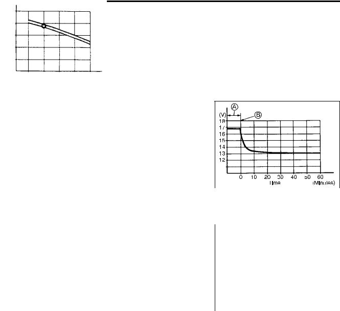
RECHARGING OPERATION
• Using the multi circuit tester, check the battery voltage. If the voltage reading is the 12.0 V (DC) and less, recharge the battery with a battery charger.
A Charging period
B Stop charging
* When recharging the battery, remove the battery |
|
|
|
|
|
|
|
|
||
from the motorcycle. |
|
|
|
|
|
E |
|
|
|
|
* Do not remove the caps on the battery top while |
|
|
|
|
|
|
||||
recharging. |
|
|
|
|
|
|
|
|
||
Recharging time: 5 A for 1 hour or 1.2 A for 5 to 10 hours |
|
|
|
|
|
|
|
|||
|
|
(V) |
|
|
|
|
||||
|
|
|
|
L |
|
|
|
|
||
|
|
P |
14 |
|
|
|
|
|||
|
13 |
|
|
|
|
|||||
Be careful not to permit the charging |
current to |
|
|
|
|
|
|
|
||
|
|
|
12 |
|
|
|
|
|||
exceed 5 A at any time. |
M |
|
|
|
|
|
|
|
||
|
|
|
|
|
|
|
|
|||
|
|
|
|
11 |
|
|
|
|
||
• After recharging, wait for 30 minutes and more and check the |
|
|
|
|
|
|
||||
|
|
10 |
|
|
|
|
||||
|
A |
|
|
|
|
|
|
|||
battery voltage with a multi circuit tester. |
|
|
|
|
|
|
|
|
|
|
|
S |
|
|
|
|
100 |
75 |
50 |
25 |
0 (%) |
• If the battery voltage is the 12.5 V and less, recharge the bat- |
|
|
Battety charged condition |
|||||||
tery again. |
|
|
|
|
|
|||||
|
|
|
|
|
|
|
|
|
|
|
|
|
|
|
|
|
|
|
|
|
|
•If battery voltage is still 12.5 V and less, after recharging, replace the battery with a new one.
•When the motorcycle is not used for a long period, check the battery every 1 month to prevent the battery discharge.