

8-36 |
CHASSIS |
|
|
|
|
|
HANDLEBARS |
|
|
|
|
|
|
CONSTRUCTION |
|
|
|
|
|
|
|
|
|
E |
|
|
|
|
|
|
L |
|
|
|
|
|
P |
|
|
|
|
|
|
M |
|
D |
|
|
|
|
A |
|
FW |
|
|
|
|
|
|
|
|
|
|
S |
|
|
|
|
|
1 |
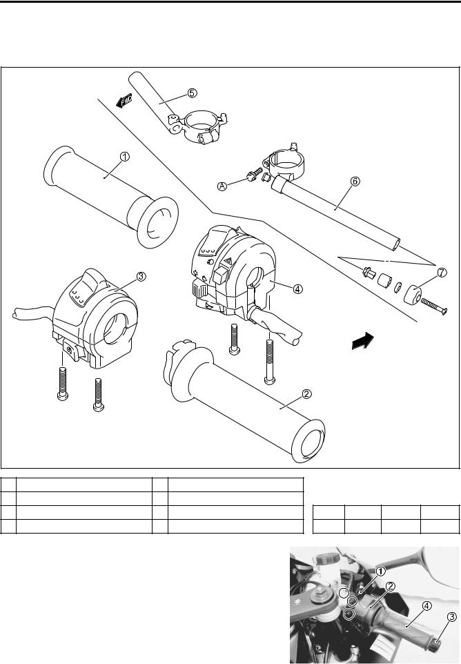
Left handle grip |
5 Handlebar (RH) |
|
|
|
|
2 |
Right handle throttle grip |
6 Handlebar (LH) |
|
|
|
|
3 |
Right handle switch |
7 Handle balancer |
ITEM |
N·m |
kgf-m |
lb-ft |
4 |
Left handle switch |
A Handlebar clamp bolt |
A |
23 |
2.3 |
16.5 |
REMOVAL
•Remove the brake master cylinder 1.
•Remove the right handle switch 2.
•Remove the handle balancer 3.
•Remove the right handle throttle grip 4.
CHASSIS 8-37
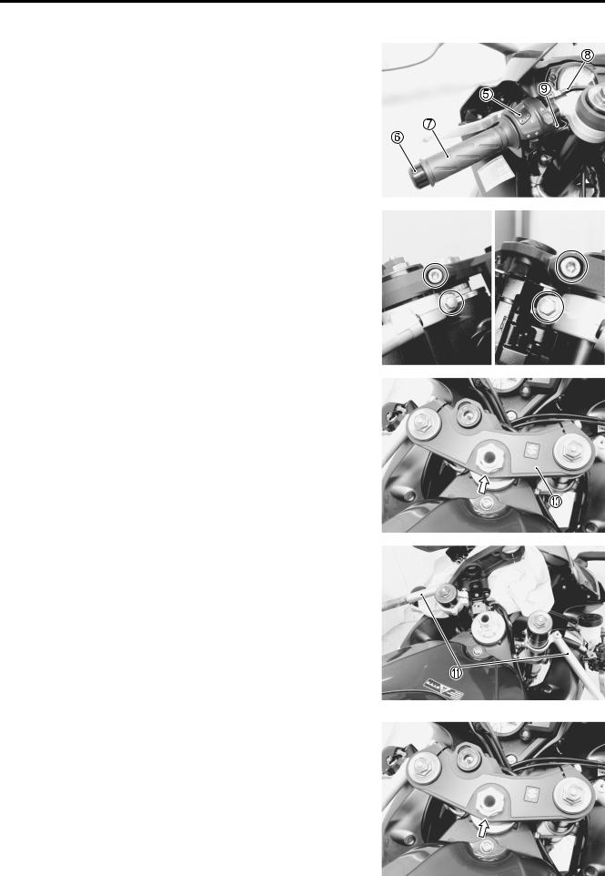
• Remove the left handle switch 5 and disconnect the clutch lever switch lead wire.
• Remove the handle balancer 6.
• Remove the left handle grip 7.
• Disconnect the clutch cable 8.
• Remove the clutch lever holder 9.
•Loosen the handlebar clamp bolts and front fork upper clamp bolts.
|
|
E |
|
L |
|
• Remove the steering stem upper bracket 0 by removing the |
|
|
steering stem head nut. |
|
|
NOTE: |
|
|
M |
|
|
Place a rag under the steering stem upper bracketPto prevent |
|
|
scratching the body cowling and the air intake pipes. |
|
|
A |
|
|
S |
|
|
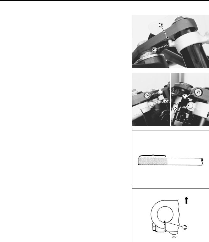
• Remove the handlebars A by sliding them upward.
INSTALLATION
Install the handlebars in the reverse order of removal. Pay attention to the following points:
•Install the handlebars temporarily.
•Install the steering stem upper bracket and washer. ( 8-34)
8-38 CHASSIS
• Insert the protrusion A of the handlebars into the hole B of the steering stem upper bracket.
•Tighten the front fork upper clamp bolts 1 and handlebar clamp bolts 2 to the specified torque.
Front fork upper clamp bolt: 23 N·m (2.3 kgf-m, 16.5 lb-ft)
Handlebar clamp bolt: 23 N·m (2.3 kgf-m, 16.5 lb-ft)
|
|
|
|
E |
|
|
|
|
|
|
|
• Apply a handle grip bond onto the left handlebar before |
L |
|
|||
installing the handlebar grip. |
P |
|
|
||
|
M |
|
|
Handle grip bond |
|
|
|
|
|
|
|
|
A |
|
|
|
|
S |
|
|
|
|
|
|
|
|
|
||
•Install the clutch lever holder, align the holder’s mating surface C with punched mark D on the handlebar.
• Install the front brake master cylinder. ( 8-74) |
Up side |
|
CHASSIS 8-39
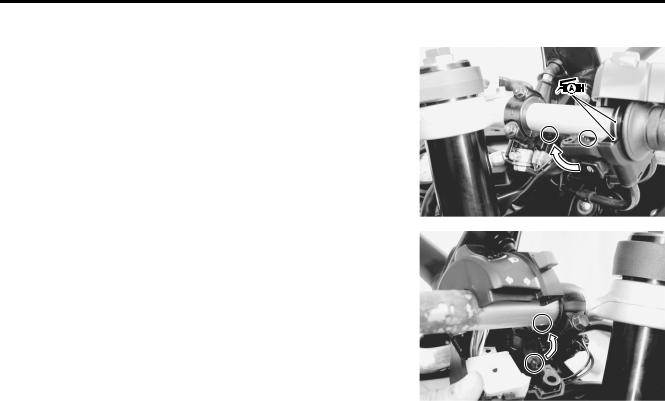
•Apply the SUZUKI SUPER GREASE “A” to the throttle cables and cable drum.
99000-25010: SUZUKI SUPER GREASE “A”
(or equivalent grease)
• When remounting the right and left handle switches, engage the stopper with the handlebar hole.
|
|
E |
|
L |
|
After installing the steering, the following adjustments are |
|
|
required before driving. |
P |
|
• Cable routing ( 10-17) |
|
|
|
|
|
• Throttle cable play ( 2-15) |
|
|
• Clutch lever play ( 2-16) |
M |
|
|
|
|
A |
|
|
S |
|
|