


9-2 ELECTRICAL SYSTEM
ELECTRICAL SYSTEM
CONTENTS
RELAYS ...................................................................................................... |
|
9-37 |
|
TURN SIGNAL/SIDE-STAND RELAY .................................................. |
|
9-37 |
|
STARTER RELAY ................................................................................. |
|
9-37 |
|
FUEL PUMP RELAY ............................................................................. |
|
9-37 |
|
COOLING FAN RELAY......................................................................... |
|
9-37 |
|
IGNITION SWITCH REMOVAL ............................................................. |
|
9-38 |
|
IGNITION SWITCH INSTALLATION..................................................... |
|
9-38 |
|
SWITCHES INSPECTION ..................................................................... |
|
9-39 |
|
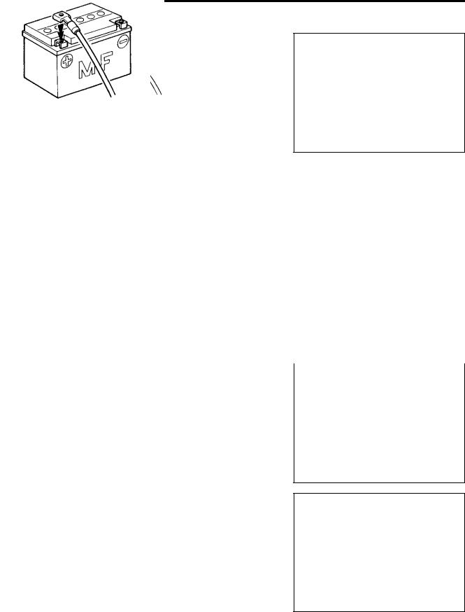
BATTERY .................................................................................................... |
|
9-40 |
|
SPECIFICATIONS ................................................................................. |
|
9-40 |
|
INITIAL CHARGING .............................................................................. |
|
9-40 |
|
SERVICING ........................................................................................... |
E |
9-42 |
|
RECHARGING OPERATION |
9-42 |
||
|
|||
|
|
|
|
|
L |
|
|
P |
|
||
M |
|
|
|
A |
|
|
|
S |
|
|
|
ELECTRICAL SYSTEM 9-3
CAUTIONS IN SERVICING
CONNECTOR
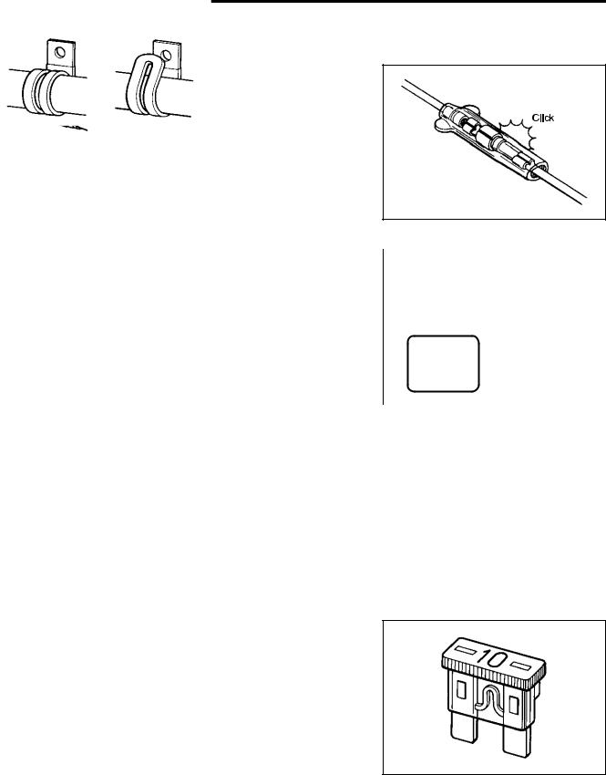
•When connecting a connector, be sure to push it in until a click is felt.
•Inspect the connector for corrosion, contamination and breakage in its cover.
COUPLER |
|
|
|
|
|
|
|
|
|
|
|
|
Click |
|
|
• With a lock type coupler, be sure to release the lock when dis- |
|
|
|
|
|||
connecting, and push in fully to engage the lock when con- |
|
|
|
|
|||
necting. |
|
|
|
|
|
|
|
• When disconnecting the coupler, be sure to hold the coupler |
|
|
|
|
|||
itself and do not pull the lead wires. |
|
|
|
E |
|
|
|
• Inspect each terminal on the coupler for being loose or bent. |
|
|
|
||||
• Inspect each terminal for corrosion and contamination. |
L |
|
|
||||
|
|
|
|
|
|||
CLAMP |
|
P |
|
|
|
|
|
|
|
|
|
|
|||
|
|
|
|
|
|||
|
|
|
|
|
|
|
|
• Clamp the wire harness at such positions as indicated in |
|
|
|
|
|||
|
A |
|
|
|
CORRECT |
INCORRECT |
|
“WIRING HARNESS ROUTING”. ( M10-17 to -20) |
|
|
|||||
|
|
|
|
|
|||
|
S |
|
|
|
|
|
|
• Bend the clamp properly so that the wire harness is clamped |
|
|
|
|
|||
securely. |
|
|
|
|
|
|
|
• In clamping the wire harness, use care not to allow it to hang |
|
|
|
|
|||
down. |
|
|
|
|
|
|
|
• Do not use wire or any other substitute for the band type |
|
|
|
|
|||
clamp. |
|
|
|
|
|
|
|
FUSE
•When a fuse blows, always investigate the cause to correct it and then replace the fuse.
•Do not use a fuse of a different capacity.
•Do not use wire or any other substitute for the fuse.
ELECTRICAL SYSTEM 9-5
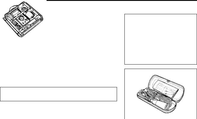
USING THE MULTI-CIRCUIT TESTER
•Properly use the multi-circuit tester + and - probes. Improper use can cause damage to the motorcycle and tester.
•If the voltage and current values are not known, begin measuring in the highest range.
•When measuring the resistance, make sure that no voltage is applied. If voltage is applied, the tester will be damaged.
•After using the tester, be sure to turn the switch to the OFF position.
09900-25008: Multi-circuit tester set
Before using the multi-circuit tester, read its instruction manual.
NOTE: |
|
|
|
* When connecting the multi-circuit tester, use the needle |
E |
||
pointed probe to the back side of the lead wire coupler and |
|||
|
|
|
|
connect the probes of tester to them. |
L |
||
|
|
|
|
* Use the needle pointed probe to prevent the rubber of the |
|
|
|
water proof coupler from damage. |
P |
|
|
|
|
|
|
09900-25009: Needle pointed probe set |
|
|
|
M |
|
|
|
A |
|
|
|
S |
|
|
|