

acer extensa 5635
.pdfRemoving the WLAN Module
1.See “Removing the Lower Door” on page 44.
2.Disconnect the Antenna cables from the WLAN Module.
NOTE: The black cable attaches to the MAIN terminal and the white cable attaches to the AUX terminal.
NOTE: When reattaching the antennas, ensure the cables are tucked into the chassis to prevent damage.
3.Remove the two screws securing the WLAN Module to the Mainboard
Step |
|
Size |
Quantity |
Screw Type |
|
|
|
|
|
WLAN Module |
M2.5*4 |
|
2 |
|
|
|
|
|
|
Chapter 3 |
51 |
Downloaded from www.Manualslib.com manuals search engine
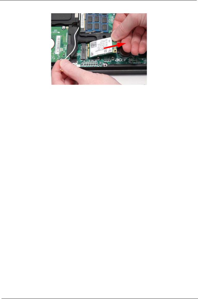
4.Detach the WLAN Module from the WLAN socket.
52 |
Chapter 3 |
Downloaded from www.Manualslib.com manuals search engine
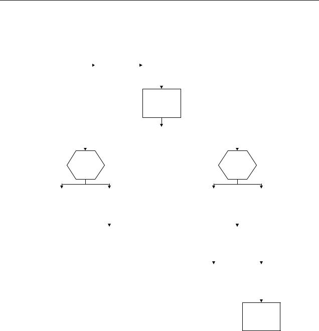
Main Unit Disassembly Process
Main Unit Disassembly Flowchart
Remove External |
|
|
Remove |
|
|
Remove |
|
Modules before |
|
|
|
|
|||
|
|
Switch Cover |
|
|
Keyboard |
||
proceeding |
|
|
|
|
|||
|
|
|
|
|
|
|
|
|
|
|
|
|
|
|
|
|
|
|
|
|
|
|
|
Remove
LCD Module
|
|
Remove |
|
|
|
|
Upper Cover |
|
|
|
|
|
|
|
Upper |
|
Lower |
||
|
||||
Cover |
|
Cover |
||
Remove |
|
Remove |
|
Remove |
|
|
|
Remove |
|||
TouchPad |
|
|
|
||||||||
|
Speaker Module |
|
Bluetooth |
|
|
|
USB Board |
||||
Bracket |
|
|
|
||||||||
|
|
|
|
|
|
|
|
|
|
|
|
|
|
|
|
|
|
|
|
|
|
|
|
|
|
|
|
|
|
|
|
|
|
|
|
Remove |
|
|
|
|
|
Remove |
|
|
||||
Microphone |
|
|
|
|
Mainboard |
|
|
|||||
|
|
|
|
|
|
|
|
|
|
|
|
|
|
|
|
|
|
|
|
|
|
|
|
||
|
|
|
|
|
|
|
|
|
|
|
|
|
|
|
Remove |
|
|
|
|
Remove |
|||||
|
|
Hinge Supports |
|
|
|
Thermal Module |
||||||
|
|
|
|
|
|
|
|
|
|
|
|
|
|
|
|
|
|
|
|
|
|
|
|
|
|
Remove
CPU
Screw List
|
|
Step |
Screw |
Quantity |
Part No. |
|
|
|
|
|
|
|
|
|
|
Switch Cover |
M2.5*2 |
3 |
86.EDM07.002 |
|
|
|
|
|
|
|
|
|
|
|
M2.5*5 |
4 |
86.ARE07.003 |
|
|
|
|
|
|
|
|
|
|
LCD Module |
M2.5*5 |
6 |
86.ARE07.003 |
|
|
|
|
|
|
|
|
|
|
Upper Cover |
M2.5*5 |
18 |
86.ARE07.003 |
|
|
|
|
|
|
|
|
|
|
|
M2.5*4 |
4 |
86.EDM07.003 |
|
|
|
|
|
|
|
|
|
|
TouchPad Bracket |
M2.5*3 |
2 |
86.TPK07.003 |
|
|
|
|
|
|
|
|
|
|
Speaker Module |
M2.5*3 |
2 |
86.TPK07.003 |
|
|
|
|
|
|
|
|
|
|
Bluetooth Board |
M2*3 |
1 |
86.ARE07.002 |
|
|
|
|
|
|
|
|
|
|
USB Board |
M2.5*5 |
2 |
86.ARE07.003 |
|
|
|
|
|
|
|
|
|
|
Mainboard |
M2.5*5 |
1 |
86.ARE07.003 |
|
|
|
|
|
|
|
|
|
|
Hinge Supports |
M2.5*4 |
4 |
86.EDM07.003 |
|
|
|
|
|
|
|
|
|
|
|
|
|
|
|
Chapter 3 |
|
|
53 |
|||
Downloaded from www.Manualslib.com manuals search engine
Removing the Switch Cover
1.See “Removing the Battery Pack” on page 42.
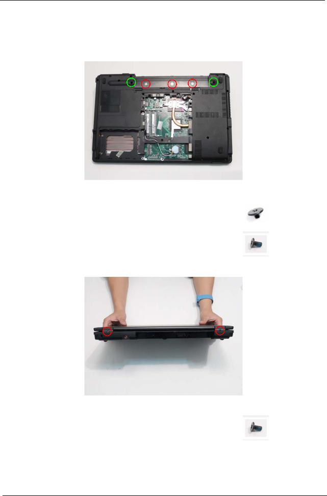
2.Remove the five screws securing the Switch Cover to the Upper Cover.
NOTE: The screws marked with green callouts are also marked on the Lower Cover with the letters KB.
Step |
Size |
Quantity |
Screw Type |
|
|
|
|
Switch Cover |
M2.5*2 |
3 |
|
(red callout) |
|
|
|
|
|
|
|
Switch Cover |
M2.5*5 |
2 |
|
(green callout) |
|
|
|
|
|
|
|
3.Remove the two screws on the spine of the Notebook securing the Switch Cover to the LCD Brackets.
Step |
|
Size |
Quantity |
Screw Type |
|
|
|
|
|
Switch Cover |
M2.5*5 |
|
2 |
|
|
|
|
|
|
54 |
Chapter 3 |
Downloaded from www.Manualslib.com manuals search engine

4.Turn the computer over and open the LCD Panel to the full extent.
IMPORTANT: Do not use metal tools to remove the Switch Cover. Using metal tools may permanently damage the casing.
5.Insert a suitable plastic tool in to the cutout located above the keypad Num Lock key, and pry the Switch Cover away from the Upper Cover as shown.
6.Working from right to left, lift the Switch Cover away from the Upper Cover as shown.
7.Remove the Switch Cover from the Upper Cover.
Chapter 3 |
55 |
Downloaded from www.Manualslib.com manuals search engine
Removing the Keyboard
1.See “Removing the Switch Cover” on page 54.
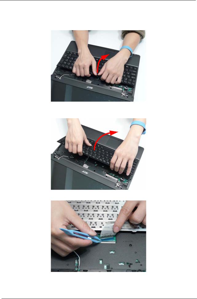
2.Lift the centre of Keyboard up as shown to release the four securing clips on the Upper Cover.
IMPORTANT: Do not remove the Keyboard from the computer; the Keyboard FFCs are still connected.
3.Turn the Keyboard over and place it on the TouchPad.
4.Disconnect the Keyboard cable by opening the FFC latch and removing the cable from the Mainboard.
5.Remove the Keyboard from the Upper Cover.
56 |
Chapter 3 |
Downloaded from www.Manualslib.com manuals search engine
Removing the LCD Module
1.See “Removing the Keyboard” on page 56.
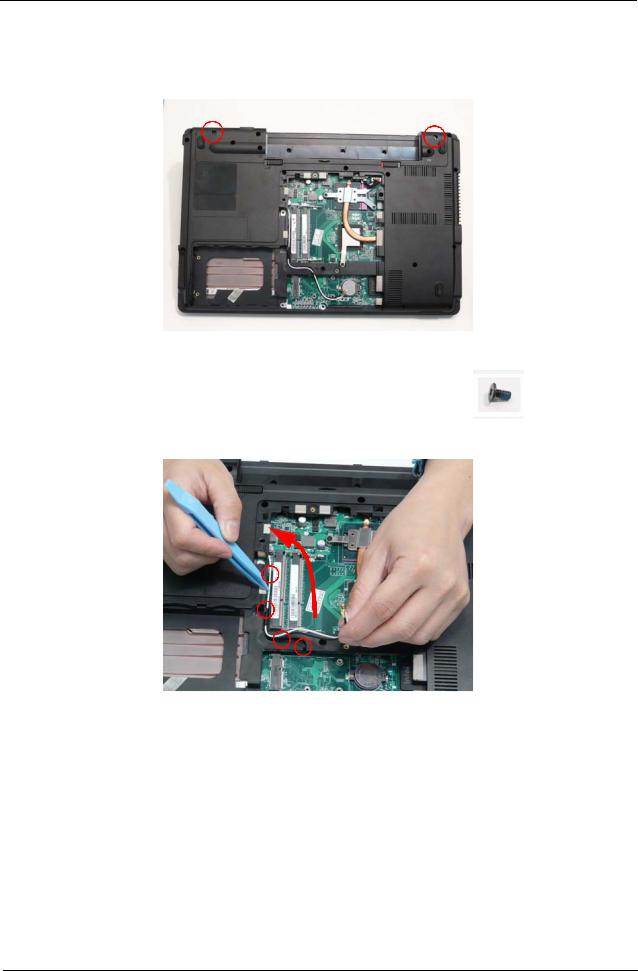
2.Turn the computer over. Remove the two screws securing the LCD Module to the Lower Cover.
Step |
|
Size |
Quantity |
Screw Type |
|
|
|
|
|
LCD Module |
M2.5*5 |
|
2 |
|
|
|
|
|
|
3.Remove the Antenna cables from the cable channel. Ensure that the cables are free from all cable clips.
Chapter 3 |
57 |
Downloaded from www.Manualslib.com manuals search engine

4.Pull the Antenna cables through the Upper Cover as shown. Ensure that the Antennas are completely free from the cover.
5.Remove the Antenna from the cable channel all the way to the Hinge Well. Ensure that the cables are free from all cable clips.
6.Grasp the pull tab and lift upward as shown to disconnect the LVDS cable.
|
|
|
|
|
|
|
|
58 |
|
Chapter 3 |
|
Downloaded from www.Manualslib.com manuals search engine
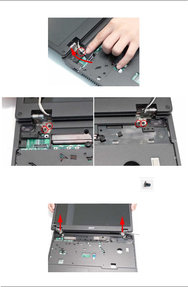
7.Remove the LVDS cable from the cable channel all the way to the Hinge Well. Ensure that the cable is free from the cable clip.
8.Remove the four screws securing the LCD Module to the Lower Cover.
Step |
|
Size |
Quantity |
Screw Type |
|
|
|
|
|
LCD Module |
M2.5*5 |
|
4 |
|
|
|
|
|
|
9.Using both hands, lift the LCD Module clear of the Lower Cover.
Chapter 3 |
59 |
Downloaded from www.Manualslib.com manuals search engine
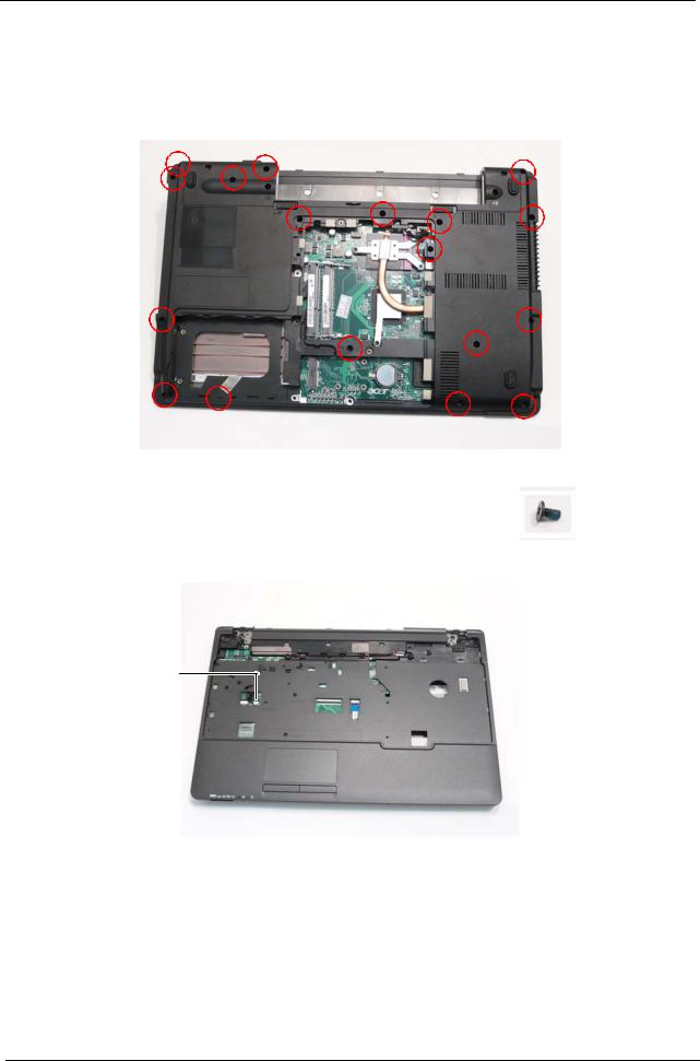
Removing the Upper Cover
IMPORTANT: The TouchPad is supplied as part of the Upper Cover. If the TouchPad is defective, replace the entire Upper Cover.
1.See “Removing the LCD Module” on page 57.
2.Turn the computer over. Remove the eighteen screws on the bottom panel.
Step |
|
Size |
Quantity |
Screw Type |
|
|
|
|
|
Upper Cover |
M2.5*5 |
|
18 |
|
|
|
|
|
|
3.Turn the computer over and disconnect the following cables from the Mainboard.
A
B 
 C
C
NOTE: Avoid pulling on cables directly to prevent damage to the connectors.
NOTE: Use the pull-tabs on FFC cables whenever available to prevent damage.
60 |
Chapter 3 |
Downloaded from www.Manualslib.com manuals search engine