

acer extensa 5635
.pdfRemoving the LCD Panel
1.See “Removing the LCD Bezel” on page 79.
2.Remove the four securing screws from the LCD Panel.
Step |
|
Size |
Quantity |
Screw Type |
|
|
|
|
|
LCD Panel |
M2.5*5 |
|
4 |
|
|
|
|
|
|
3.Lift the LCD Panel, front edge first, and turn it over to expose the Camera cable.
Chapter 3 |
81 |
Downloaded from www.Manualslib.com manuals search engine
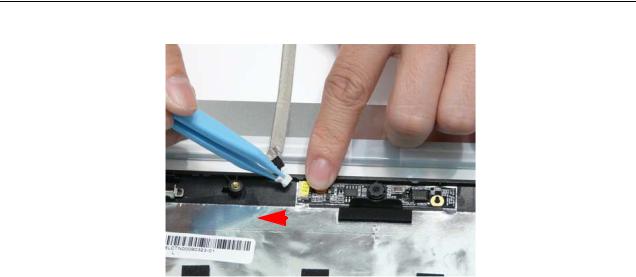
4.Disconnect the Camera cable and remove the LCD Panel.
|
|
|
|
|
|
|
|
82 |
|
Chapter 3 |
|
Downloaded from www.Manualslib.com manuals search engine
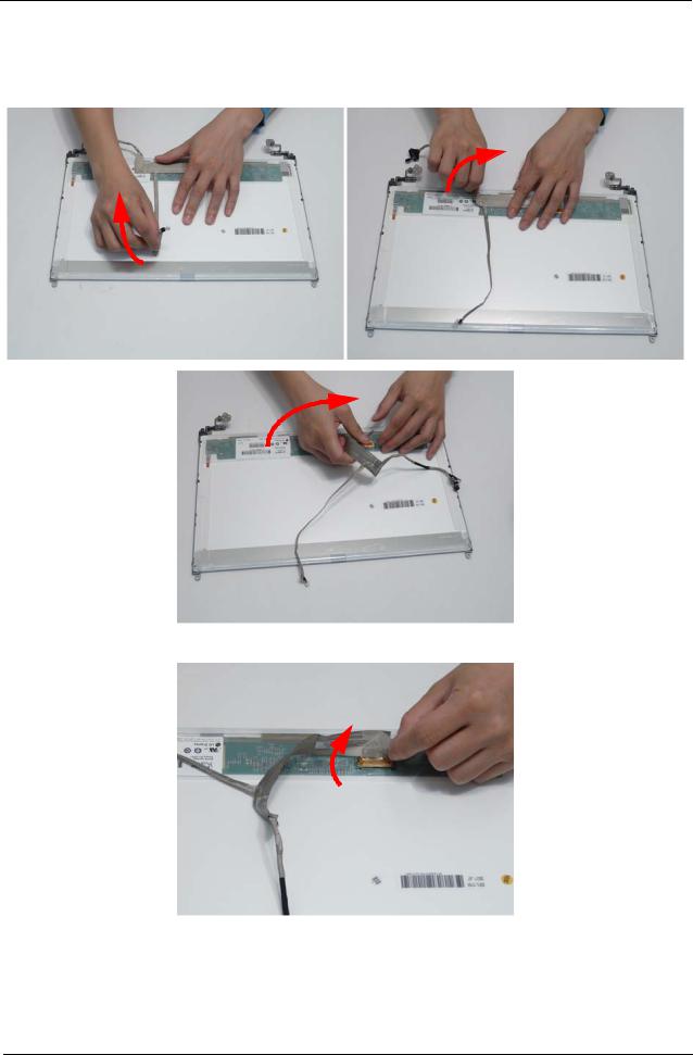
Removing the FPC Cable and LCD Brackets
1.See “Removing the LCD Panel” on page 81.
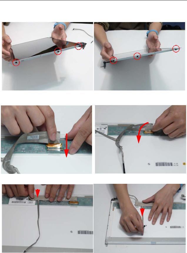
2.Lift the cable away from the LCD Panel to detach the adhesive securing it in place.
3.Carefully lift the adhesive tape securing the cable to the panel.
Chapter 3 |
83 |
Downloaded from www.Manualslib.com manuals search engine
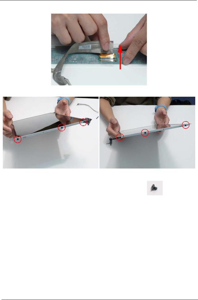
4.Disconnect the cable from the LCD panel as shown.
5.Remove the six securing screws (three each side) from the LCD Panel brackets.
Step |
|
Size |
Quantity |
Screw Type |
|
|
|
|
|
LCD Brackets |
M2*3 |
|
6 |
|
|
|
|
|
|
6.Remove the brackets from the LCD Panel.
84 |
Chapter 3 |
Downloaded from www.Manualslib.com manuals search engine
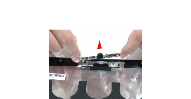
Removing the Camera Board
1.See “Removing the LCD Panel” on page 81.
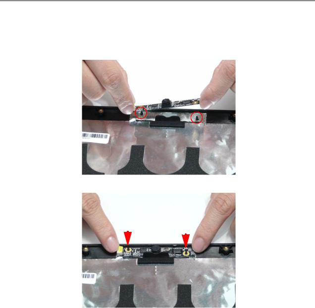
2.Remove the Camera Board from the LCD Module.
|
|
|
|
|
|
|
|
Chapter 3 |
85 |
||
Downloaded from www.Manualslib.com manuals search engine
LCD Module Reassembly Procedure
Replacing the Camera Board
1.Ensure that the locating pins are correctly positioned and place the Camera Board in the LCD Module.
2.Press down to secure it in place
|
|
|
|
|
|
|
|
|
|
|
|
|
|
|
|
|
|
|
|
|
|
|
|
86 |
|
|
|
Chapter 3 |
|
Downloaded from www.Manualslib.com manuals search engine
Replacing the LCD Brackets and FPC Cable
1.Secure the brackets to the panel using six bracket screws (three each side).
2.Insert the LCD Cable into the panel connector as shown.
3.Secure the connector by replacing the adhesive strip as shown.
4.Replace the LCD cable as shown. Press down as indicated to secure the cable in place.
|
|
|
|
|
|
|
|
|
|
|
|
|
|
|
|
|
|
|
|
|
|
|
|
Chapter 3 |
87 |
||||
Downloaded from www.Manualslib.com manuals search engine
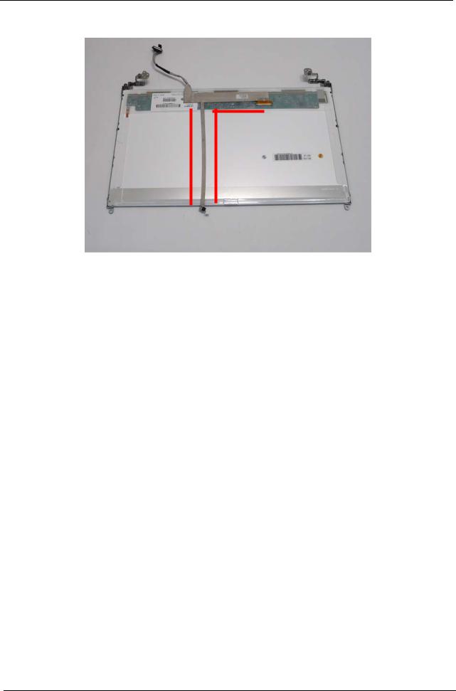
IMPORTANT:Ensure that the LCD Cable runs as shown to avoid trapping when the Bezel is replaced.
88 |
Chapter 3 |
Downloaded from www.Manualslib.com manuals search engine

Replacing the LCD Panel
1.Place the LCD Panel adjacent to the LCD Cover and reconnect the Camera cable.
2. Turn the panel over and place it in the LCD Cover. IMPORTANT: Ensure that the cables are not trapped under the panel.
3.Replace the four screws to secure the panel in place.
|
Step |
|
Size |
Quantity |
Screw Type |
|
|
|
|
|
|
|
|
|
LCD Panel |
M2.5*5 |
|
4 |
|
|
|
|
|
|
|
|
|
|
|
|
|
|
|
|
Chapter 3 |
89 |
Downloaded from www.Manualslib.com manuals search engine
Replacing the LCD Bezel
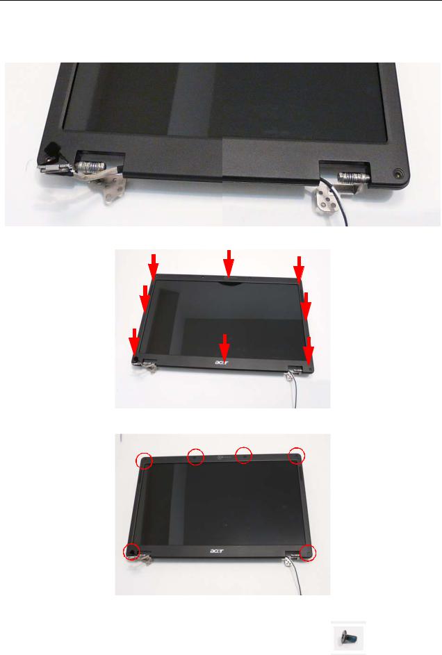
1. Place the Bezel onto the LCD Module ensuring that the cables exit the module as shown and are not trapped between the bezel and the cover.
2.Press down around the perimeter of the Bezel to snap it in to place.
3.Replace the six screws and screw caps for the LCD Bezel.
|
Step |
|
Size |
Quantity |
Screw Type |
|
|
|
|
|
|
|
|
|
LCD Bezel |
M2.5*5 |
|
6 |
|
|
|
|
|
|
|
|
|
|
|
|
|
|
|
|
90 |
Chapter 3 |
Downloaded from www.Manualslib.com manuals search engine