

acer extensa 5635
.pdfItem |
|
Specification |
|
|
|
|
|
|
|
Typical Power Consumption |
5.6 |
5.3 |
4.9 |
4.5 |
(watt) |
|
|
|
|
|
|
|
|
|
Weight (without inverter) |
450 |
355 |
360 |
350 |
|
|
|
|
|
Physical Size (mm) |
360x210x5.5 |
359.3x209.5x |
359.3x209.5x |
324x192.5x5. |
|
|
5.2 |
5.5 |
2 |
Electrical Interface |
1 ch. LVDS |
1 ch. LVDS |
LVDS |
LVDS |
|
|
|
|
|
Viewing Angle (degree) |
|
|
|
|
Horizontal (Right)/CR = 10 (Left) |
45/45 (typical) |
45/45 (typical) |
45/45 (typical) |
40/40 (min) |
Vertical (Upper)/CR = 10 (Lower) |
15/35 (typical) |
20/45 (typical) |
15/35 (typical) |
10/30 (min) |
|
|
|
|
|
Audio Interface
Item |
|
Specifications |
|
|
|
|
|
|
|
Audio Controller |
• Conexant CX-20561-15Z Azalia Codec |
|
||
|
• Amplifier GMT G1441 |
|
|
|
|
|
|
|
|
Audio onboard or option |
Built-in |
|
|
|
|
|
|
|
|
Mono or Stereo |
Stereo |
|
|
|
|
|
|
|
|
Resolution |
2.1 |
|
|
|
|
|
|
|
|
Compatibility |
Headphone-out with S/PDIF, Line-In and Microphone-In.2 stereo ADCs |
|
||
|
support 16/20/24-bit PCM format recording simultaneously. |
|
||
|
|
|
|
|
Sampling Rate. |
All DACs supports 16/20/24-bit, 44.1k/48k/96k/192kHz sample rate.All |
|
||
|
ADCs supports 16/20/24-bit, 44.1k/48k/96k/192kHz sample rate.Two |
|
||
|
independent S/PDIF-OUT converters support 16/20/24-bit, 44.1k/48k/88.2k/ |
|
||
|
96k/192kHz sample rate. One for normal S/PDIF output, the other one |
|
||
|
output an independent digital stream to HDMI transmitter. |
|
||
|
|
|
|
|
Internal Microphone |
• Digital MICRO PHONE ZK2(HFM-M101-006-L19-G) |
|
||
|
• Digital MICRO PHONE ZK2(A-OA2408FM-018) |
|
||
|
|
|
|
|
Internal speaker/ |
Two Med-High Speakers (2W/4Ohm |
) and one Subwoofer (3W/4Ohm) |
|
|
Quantity |
|
|
|
|
|
|
|
|
|
LAN Interface |
|
|
|
|
|
|
|
|
|
Item |
|
|
Specification |
|
|
|
|
|
|
LAN Chipset |
|
Atheros AL8131L-Al1 |
E-R/AL008131002 Gigabit Ethernet |
|
|
|
LAN Controller |
|
|
|
|
|
|
|
Features |
|
• Combines a 10/100/1000BASE-T GbE media access |
|
|
|
|
controller (MAC), a triple-speed Ethernet physical layer |
|
|
|
|
transceiver (PHY), and a PCI Express bus interface. |
|
|
|
|
• Compliant with IEEE 802.3u specification for 10/ |
|
|
|
|
100Mbps Ethernet and IEEE 802.3ab specification for |
|
|
|
|
1000Mbps Ethernet. |
|
|
|
|
• Combines pulse shaping, Tx/Rx PCS, echo canceller, |
|
|
|
|
NEXT canceller, equalizer, decoder, and timing recovery |
|
|
|
|
functions to deliver robust signal performance in noisy |
|
|
|
|
environments. |
|
|
|
|
• Supports checksum offload features for IP, TCP, and |
|
|
|
|
UDP, lowering CPU utilization and optimizing network |
|
|
|
|
performance. |
|
|
|
|
• Supports advanced power management functions, |
|
|
|
|
including Wake-On-LAN (WOL) and AMD Magic |
|
|
|
|
Packet™ |
|
|
|
|
|
|
|
Chapter 1 |
21 |
Downloaded from www.Manualslib.com manuals search engine

Keyboard
Item |
|
Specification |
|
|
|
Type |
Flat keyboard |
|
|
|
|
Total number of keypads |
84 |
|
|
|
|
Windows logo key |
Yes |
|
|
|
|
Internal & external keyboard work |
Plug USB keyboard to the USB port directly: Yes |
|
simultaneously |
|
|
|
|
|
Mini Card |
|
|
|
|
|
Item |
|
Specification |
|
|
|
Number Supported |
2 |
|
|
|
|
Features |
• 2 mini card slot (1 for 3G / WiMax (full-size) and 1 for |
|
|
|
WLAN (half-size) |
|
• Embedded 3G module and built-in 2 antenna (combo |
|
|
|
wireless + 3G) on top of LCD |
|
|
|
3G Card |
|
|
|
|
|
Item |
|
Specification |
|
|
|
Features |
• 3G card in mini card slot for 3G/ WiMAX (full-size) |
|
|
• Control by USB interface |
|
|
• User accessible SIM card by battery removal |
|
|
• Antenna: Has to be placed on the sides of LCD in A/B |
|
|
|
cover |
|
|
|
Bluetooth interface |
|
|
|
|
|
Item |
|
Specification |
|
|
|
Chipset |
• FOXCON T60H928.01 LF Bluetooth miniUSB module |
|
|
|
|
Features |
• Embedded USB solution with antenna |
|
|
• |
Bluetooth 2.0+EDR |
|
• Bluetooth control for BT optical mouse |
|
|
|
|
Wireless LAN |
|
|
|
|
|
Item |
|
Specification |
|
|
|
Type |
IEEE802.11 b/g Half PCI-e Card |
|
|
|
|
Features |
• |
IEEE 802.11 b/g |
|
• PCI-Express Half Mini card (H2 type) |
|
|
|
|
Battery |
|
|
|
|
|
Item |
|
Specification |
|
|
|
Vendor & model name |
SANYO UM-2008BW, PANASONIC UM-2008B, SIMPLO |
|
|
UM-2008A |
|
|
|
|
Battery Type |
Li-ion |
|
|
|
|
Pack capacity |
4400/5800 mAh |
|
|
|
|
Number of battery cell |
6 |
|
|
|
|
Package configuration |
3S2P |
|
|
|
|
22 |
Chapter 1 |
Downloaded from www.Manualslib.com manuals search engine

Chapter 2
System Utilities
BIOS Setup Utility
The BIOS Setup Utility is a hardware configuration program built into your computer’s BIOS (Basic Input/ Output System).
Your computer is already properly configured and optimized, and you do not need to run this utility. However, if you encounter configuration problems, you may need to run Setup. Please also refer to Chapter 4 Troubleshooting if a problem arises.
To activate the BIOS Utility, press F2 during POST (when Press <F2> to enter Setup message is prompted on the bottom of screen).
Press F2 to enter setup. The default parameter of F12 Boot Menu is set to “disabled”. If you want to change boot device without entering BIOS Setup Utility, please set the parameter to “enabled”.
Press <F12> during POST to enter multi-boot menu. In this menu, user can change boot device without entering BIOS SETUP Utility.
Navigating the BIOS Utility
There are six menu options: Information, Main, Advanced, Security, Power, Boot, and Exit. Follow these instructions:
•To choose a menu, use the left and right arrow keys.
•To choose an item, use the up and down arrow keys.
•To change the value of a parameter, press F5 or F6.
•A plus sign (+) indicates the item has sub-items. Press Enter to expand this item.
•Press Esc while you are in any of the menu options to go to the Exit menu.
•In any menu, you can load default settings by pressing F9. You can also press F10 to save any changes made and exit the BIOS Setup Utility.
NOTE: You can change the value of a parameter if it is enclosed in square brackets. Navigation keys for a particular menu are shown on the bottom of the screen. Help for parameters are found in the Item Specific Help part of the screen. Read this carefully when making changes to parameter values. Please note that system information is subject to different models.
Chapter 2 |
23 |
Downloaded from www.Manualslib.com manuals search engine

Information
The Information screen displays a summary of your computer hardware information.
|
|
|
|
|
|
Phoenix SecureCore(tm) Setup Utility |
|
|
|
|
|||
|
|
Information |
|
Main |
Security Boot |
Exit |
|
|
|
|
|
|
|
|
|
|
|
|
|
|
|
|
|
|
|
|
|
|
|
CPU Type |
|
|
Intel(R) Core(TM)2 Duo CPU |
P6570 @ 2.10GHz |
|
||||||
|
|
CPU Speed |
|
2100MHz |
|
|
|
|
|
|
|||
|
|
IDE0 Model Name: |
WDC WD3200BEVT-22ZCT0 |
|
|
|
|
||||||
|
|
IDE0 Serial Number: |
WD-WXEZ08P30288 |
|
|
|
|
|
|||||
|
|
ATAPI Model Name: |
Optiarc DVD RW AD-7580S |
|
|
|
|
||||||
|
|
System BIOS Version: |
V0.3207C |
|
|
|
|
|
|
||||
|
|
VGA BIOS Version: |
nVidia 62.98.61.00.F9 |
|
|
|
|
|
|||||
|
|
Serial Number: |
|
Z060SK03C190917A7D2500 |
|
|
|
|
|||||
|
|
Asset Tag Number: |
|
|
|
|
|
|
|
|
|||
|
|
Product Name: |
|
|
|
|
|
|
|
|
|
||
|
|
Manufacturer Name: |
Acer |
|
|
|
|
|
|
|
|||
|
|
UUID: |
|
|
C0343F08AB34E45B45CD12447670098B8 |
|
|
|
|||||
|
|
|
|
|
|
|
|
|
|
|
|
|
|
|
|
|
|
|
|
|
|
|
|
|
|
|
|
|
|
F1 Help |
|
Select |
Item |
F5/F6 |
Change |
Values |
F9 |
Setup |
Default |
||
|
|
ESC Exit |
|
Select |
Menu |
Enter |
Select |
SubMenu |
F10 |
Save |
and Exit |
||
NOTE: The system information is subject to different models.
Parameter |
Description |
|
|
CPU Type |
This field shows the CPU type of the system. |
|
|
CPU Speed |
This field shows the speed of the CPU. |
|
|
IDE0 Model Name |
This field shows the model name of HDD installed on primary IDE master. |
|
|
IDE0 Serial Number |
This field displays the serial number of HDD installed on primary IDE master. |
|
|
System BIOS Version |
Displays system BIOS version. |
|
|
VGA BIOS Version |
This field displays the VGA firmware version of the system. |
|
|
Serial Number |
This field displays the serial number of this unit. |
|
|
Asset Tag Number |
This field displays the asset tag number of the system. |
|
|
Product Name |
This field shows product name of the system. |
|
|
Manufacturer Name |
This field displays the manufacturer of this system. |
|
|
UUID Number |
Universally Unique Identifier (UUID) is an identifier standard used in software |
|
construction, standardized by the Open Software Foundation (OSF) as part of |
|
the Distributed Computing Environment (DCE). |
|
|
24 |
Chapter 2 |
Downloaded from www.Manualslib.com manuals search engine

Main
The Main screen allows the user to set the system time and date as well as enable and disable boot option and recovery.
|
|
|
|
|
|
Phoenix SecureCode(tm) Setup Utility |
|
|
|
||||||
|
Information |
|
Main |
|
Security |
Power |
Boot |
Exit |
|
|
|
|
|||
|
|
|
|
|
|
|
|
|
|
|
|
|
|
|
|
|
System Time: |
|
|
[10:49:59]: ] |
|
|
|
|
Item Specific Help |
|
|||||
|
|
|
|
|
|
|
|
|
|
|
|||||
|
|
|
|
|
|
|
|
|
|
|
|||||
|
System Date: |
|
|
[03/03/2009] |
|
|
|
|
<Tab>, <Shift-Tab>, or |
|
|||||
|
|
|
|
|
|
|
|
|
|
|
|
|
|||
|
Total Memory: |
|
|
4094 MB |
|
|
|
|
<Enter> selects field. |
|
|||||
|
Video Memory: |
|
|
512 MB |
|
|
|
|
|
|
|
|
|||
|
Quiet Boot |
|
|
|
[Enabled] |
|
|
|
|
|
|
|
|
||
|
Network Boot |
|
|
[Enabled] |
|
|
|
|
|
|
|
|
|||
|
F12 Boot Menu |
|
|
[Disabled] |
|
|
|
|
|
|
|
|
|||
|
D2D Recovery |
|
|
[Enabled] |
|
|
|
|
|
|
|
|
|||
|
SATA Mode |
|
|
[AHCI Mode] |
|
|
|
|
|
|
|
|
|||
|
|
|
|
|
|
|
|
|
|
|
|
|
|
|
|
|
|
|
|
|
|
|
|
|
|
|
|
|
|
|
|
|
F1 Help |
|
Select |
Item |
F5/F6 |
Change |
Values |
F9 |
Setup |
Default |
|||||
|
ESC Exit |
|
Select |
Menu |
Enter |
Select |
|
SubMenu |
F10 |
Save |
and Exit |
||||
NOTE: The screen above is for your reference only. Actual values may differ.
The table below describes the parameters in this screen. Settings in boldface are the default and suggested parameter settings.
Parameter |
Description |
Format/Option |
|
|
|
System Time |
Sets the system time. The hours are displayed with 24- |
Format: HH:MM:SS |
|
hour format. |
(hour:minute:second) |
|
|
|
System Date |
Sets the system date. |
Format MM/DD/YYYY |
|
|
(month/day/year) |
|
|
|
Total Memory |
This field reports the memory size of the system. |
N/A |
|
Memory size is fixed to 4094MB. |
|
|
|
|
Video Memory |
Shows the video memory size. |
N/A |
|
|
|
Quiet Boot |
Allows startup to skip certain tests while booting, |
Option: Enabled or Disabled |
|
decreasing the time needed to boot the system. |
|
|
|
|
Network Boot |
Enables, disables the system boot from LAN (remote |
Option: Enabled or Disabled |
|
server). |
|
|
|
|
F12 Boot Menu |
Enables, disables Boot Menu during POST. |
Option: Enabled or Disabled |
|
|
|
D2D Recovery |
Enables, disables D2D Recovery function. The function |
Option: Enabled or Disabled |
|
allows the user to create a hidden partition on hard disc |
|
|
drive to store operation system and restore the system |
|
|
to factory defaults. |
|
|
|
|
SATA Mode |
Control the mode in which the SATA controller should |
Option: AHCI or IDE |
|
operate. |
|
|
|
|
Chapter 2 |
25 |
Downloaded from www.Manualslib.com manuals search engine
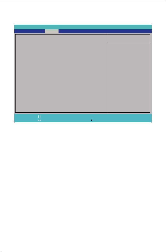
Security
The Security screen contains parameters that help safeguard and protect your computer from unauthorized use.
Information |
|
|
Phoenix SecureCore(tm) Setup Utility |
|
|
||||||
Main |
Security |
Boot |
Exit |
|
|
|
|
|
|||
Supervisor Password Is: |
Clear |
|
|
|
Item Specific Help |
||||||
|
|
|
|
|
|
||||||
User Password Is: |
|
Clear |
|
|
|
Supervisor Password |
|||||
HDD Password Is: |
|
Clear |
|
|
|
||||||
|
|
|
|
|
|
|
|
|
controls access to the |
||
Set Supervisor Password |
[Enter] |
|
|
setup utility. |
|
||||||
Set User Password |
|
[Enter] |
|
|
|
|
|
||||
Set Hdd Password |
|
[Enter] |
|
|
|
|
|
||||
Password on Boot |
|
[Disabled] |
|
|
|
|
|
||||
F1 |
Help |
|
Select |
Item |
F5/F6 |
Change |
Values |
F9 |
Setup |
Default |
|
ESC |
Exit |
|
Select |
Menu |
Enter |
Select |
SubMenu |
F10 |
Save |
and Exit |
|
The table below describes the parameters in this screen. Settings in boldface are the default and suggested parameter settings.
Parameter |
Description |
Option |
|
|
|
Supervisor Password Is |
Shows the setting of the Supervisor password |
Clear or Set |
User Password Is |
Shows the setting of the User password. |
Clear or Set |
|
|
|
HDD Password Is |
Shows the setting of the HDD password. |
Clear or Set |
|
|
|
Set Supervisor Password |
Press Enter to set the supervisor password. When |
|
|
set, this password protects the BIOS Setup Utility |
|
|
from unauthorized access. The user can not either |
|
|
enter the Setup menu nor change the value of |
|
|
parameters. |
|
|
|
|
Set User Password |
Press Enter to set the user password. When user |
|
|
password is set, this password protects the BIOS |
|
|
Setup Utility from unauthorized access. The user can |
|
|
enter Setup menu only and does not have right to |
|
|
change the value of parameters. |
|
|
|
|
Set Hdd Password |
Enter HDD password. |
|
|
|
|
Power on password |
Defines whether a password is required or not while |
Enabled or |
|
the events defined in this group happened. The |
Disabled |
|
following sub-options are all requires the Supervisor |
|
|
password for changes and should be grayed out if the |
|
|
user password was used to enter setup. |
|
|
|
|
NOTE: When you are prompted to enter a password, you have three tries before the system halts. Don’t forget your password. If you forget your password, you may have to return your notebook computer to your dealer to reset it.
26 |
Chapter 2 |
Downloaded from www.Manualslib.com manuals search engine

Setting a Password
Follow these steps as you set the user or the supervisor password:
1.Use the ↑ and ↓ keys to highlight the Set Supervisor Password parameter and press the Enter key. The Set Supervisor Password box appears:
Set Supervisor Password
Enter New Password |
[ |
|
] |
|
|||
Confirm New Password |
[ |
|
] |
2.Type a password in the “Enter New Password” field. The password length can not exceeds 8 alphanumeric characters (A-Z, a-z, 0-9, not case sensitive). Retype the password in the “Confirm New Password” field.
IMPORTANT:Be very careful when typing your password because the characters do not appear on the screen.
3.Press Enter. After setting the password, the computer sets the User Password parameter to “Set”.
4.If desired, you can opt to enable the Password on boot parameter.
5.When you are done, press F10 to save the changes and exit the BIOS Setup Utility.
Removing a Password
Follow these steps:
1.Use the ↑ and ↓ keys to highlight the Set Supervisor Password parameter and press the Enter key. The Set Password box appears:
Set Supervisor Password
Enter Current Password |
[ |
|
] |
|
|||
Enter New Password |
[ |
|
] |
Confirm New Password |
[ |
] |
|
2.Type the current password in the Enter Current Password field and press Enter.
3.Press Enter twice withouttyping anything in the Enter New Password and Confirm New Password fields. The computer then sets the Supervisor Password parameter to “Clear”.
4.When you have changed the settings, press u to save the changes and exit the BIOS Setup Utility.
Chapter 2 |
27 |
Downloaded from www.Manualslib.com manuals search engine
Changing a Password
1.Use the ↑ and ↓ keys to highlight the Set Supervisor Password parameter and press the Enter key. The Set Password box appears.
Set Supervisor Password
Enter Current Password |
[ |
|
] |
|
|||
Enter New Password |
[ |
|
] |
Confirm New Password |
[ |
] |
|
2.Type the current password in the Enter Current Password field and press Enter.
3.Type a password in the Enter New Password field. Retype the password in the Confirm New Password field.
4.Press Enter. After setting the password, the computer sets the User Password parameter to “Set”.
5.If desired, you can enable the Password on boot parameter.
6.When you are done, press F10 to save the changes and exit the BIOS Setup Utility.
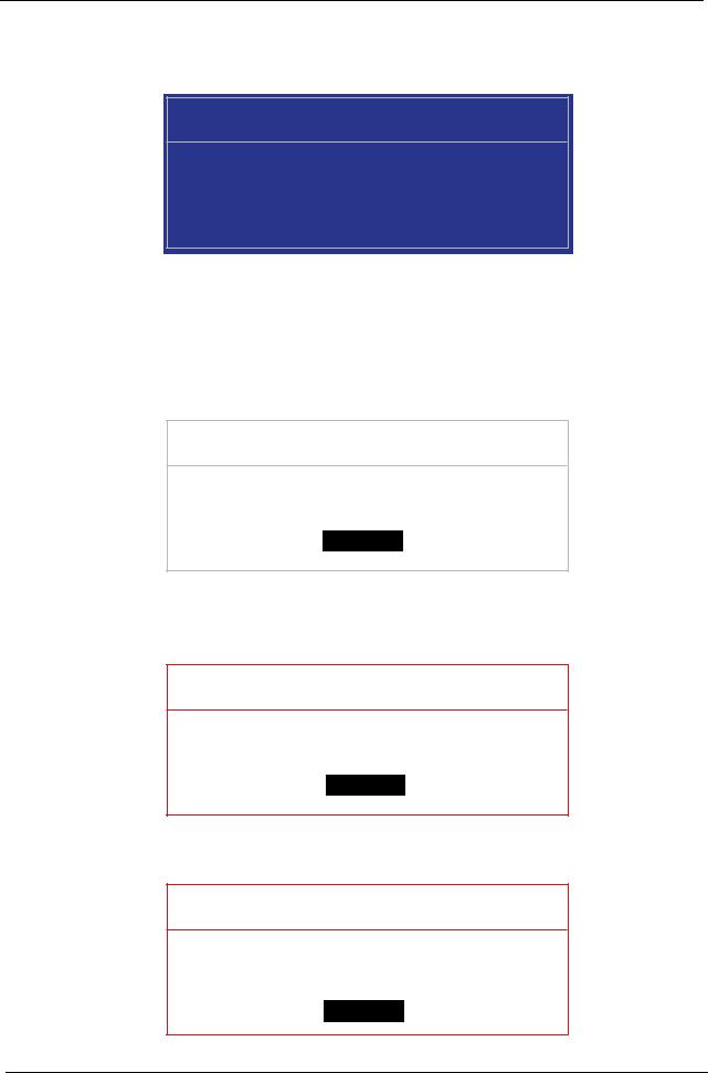
If the verification is OK, the screen will display as following.
Setup Notice
Changes have been saved.
[Continue]
The password setting is complete after the user presses Enter.
If the current password entered does not match the actual current password, the screen will show you the Setup Warning.
Setup Warning
Invalid Password.
[Continue]
If the new password and confirm new password strings do not match, the screen displays the following message.
Setup Warning
Passwords do not match. Re-enter password.
[Continue]
28 |
Chapter 2 |
Downloaded from www.Manualslib.com manuals search engine

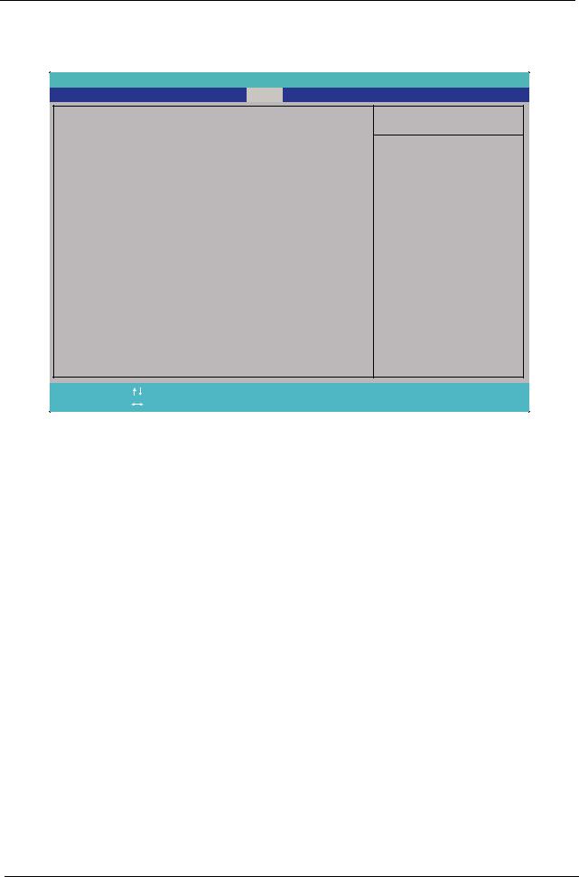
Boot
This menu allows the user to decide the order of boot devices to load the operating system. Bootable devices includes USB drives, the onboard hard disk drive and the DVD drive in the module bay.
|
|
|
Phoenix SecureCore(tm) Setup Utility |
|
|
|
|
||||||||
|
Information |
Main Security |
|
Boot |
|
Exit |
|
|
|
|
|
|
|
||
|
|
|
|
|
|
|
|
|
|
|
|
|
|
|
|
|
Boot priority order: |
|
|
|
|
|
|
|
|
Item Specific Help |
|
||||
|
|
|
|
|
|
|
|
|
|
|
|
|
|||
|
|
|
|
|
|
|
|
|
|
|
|
|
|||
|
1 |
. IDE0 : WDC WD3200BEVT-22ZCT0-(S1) |
|
|
Keys used to view or |
|
|||||||||
|
2 |
. IDE CD : Optiarc DVD RW AD-7580S |
|
|
|
||||||||||
|
3 |
. PCI LAN: Atheros Boot Agent |
|
|
|
configure devices: |
|
||||||||
|
4 |
. USB HDD : |
|
|
|
|
|
|
|
|
Up and Down arrows |
|
|||
|
5 |
. USB CDROM : |
|
|
|
|
|
|
|
|
select a device. |
|
|||
|
6 |
. USB FDC : |
|
|
|
|
|
|
|
|
<+> and <-> moves |
|
|||
|
7 |
. USB KEY : |
|
|
|
|
|
|
|
|
the device up or down. |
|
|||
|
8: |
|
|
|
|
|
|
|
|
|
<f> and <r> specifies |
|
|||
|
Excluded from boot order: |
|
|
|
|
|
|
the device fixed or |
|
||||||
|
|
|
|
|
|
|
|
|
|
|
|
removable. |
|
|
|
|
|
|
|
|
|
|
|
|
|
|
|
<x> exclude or include |
|
||
|
|
|
|
|
|
|
|
|
|
|
|
the device to boot. |
|
||
|
|
|
|
|
|
|
|
|
|
|
|
<Shift+1>enables or |
|
||
|
|
|
|
|
|
|
|
|
|
|
|
disables a device. |
|
||
|
|
|
|
|
|
|
|
|
|
|
|
<1 - 4> Loads default |
|
||
|
|
|
|
|
|
|
|
|
|
|
|
boot sequence. |
|
||
|
|
|
|
|
|
|
|
|
|
|
|
|
|
|
|
|
|
|
|
|
|
|
|
|
|
|
|
|
|
|
|
|
F1 Help |
Select |
Item |
|
F5/F6 |
Change |
Values |
F9 |
Setup |
Default |
|||||
|
ESC Exit |
Select |
Menu |
Enter |
Select |
SubMenu |
F10 |
Save |
and Exit |
||||||
Chapter 2 |
29 |
Downloaded from www.Manualslib.com manuals search engine
Exit
The Exit screen allows you to save or discard any changes you made and quit the BIOS Utility.
Information |
|
Phoenix SecureCore(tm) Setup Utility |
|
|
|
|||||
Main |
Security |
Boot |
Exit |
|
|
|
|
|||
Exit Saving Changes |
|
|
|
|
Item Specific Help |
|||||
|
|
|
|
|
|
|
||||
Exit Discarding Changes |
|
|
|
Exit System Setup and |
||||||
Load Setup Defaults |
|
|
|
|
||||||
Discard Changes |
|
|
|
|
save your changes to |
|||||
Save Changes |
|
|
|
|
|
CMOS. |
|
|
||
F1 |
Help |
|
Select |
Item |
|
F5/F6 |
Change Values |
F9 |
Setup |
Default |
ESC |
Exit |
|
Select |
Menu |
Enter |
Execute Command |
F10 |
Save |
and Exit |
|
The table below describes the parameters in this screen.
Parameter |
Description |
|
|
Exit Saving Changes |
Exit System Setup and save your changes to CMOS. |
|
|
Exit Discarding |
Exit utility without saving setup data to CMOS. |
Changes |
|
|
|
Load Setup Default |
Load default values for all SETUP item. |
|
|
Discard Changes |
Load previous values from CMOS for all SETUP items. |
|
|
Save Changes |
Save Setup Data to CMOS. |
|
|
30 |
Chapter 2 |
Downloaded from www.Manualslib.com manuals search engine