

acer extensa 5635
.pdfExternal Module Disassembly Process
External Modules Disassembly Flowchart
Turn off system and peripherals power
Disconnect power and signal cables from system
|
|
|
|
|
|
|
|
|
|
|
|
|
Remove |
|
|
Remove |
|
|
|
|
|
||||
|
|
|
|
|
|
|
|
|
|
|
|
|
Battery |
|
|
SD Dummy Card |
|
|
|
|
|
||||
|
|
|
|
|
|
|
|
|
|
|
|
|
|
|
|
|
|
|
|
|
|
|
|
|
|
|
|
|
|
|
|
|
|
|
|
|
|
|
|
|
|
|
|
|
|
|
|
|
|
||
|
|
|
|
|
|
|
|
|
|
|
|
|
|
|
|
|
|
|
|
|
|
|
|
|
|
|
|
|
|
|
|
|
|
|
|
|
|
|
Remove |
|
|
|
|
|
|
|
|
|
|
|
|
|
|
|
|
|
|
|
|
|
|
|
|
Lower Door |
|
|
|
|
|
|
|
|
|
|
|||
|
|
|
|
|
|
|
|
|
|
|
|
|
|
|
|
|
|
|
|
|
|
|
|||
|
|
|
|
|
|
|
|
|
|
|
|
|
|
|
|
|
|
|
|
|
|
|
|
|
|
|
|
|
|
|
|
|
|
|
|
|
|
|
|
|
|
|
|
|
|
|
|
|
|
|
|
|
Remove |
|
|
|
Remove |
|
|
Remove |
|
|
Remove |
|
Remove |
|
|||||||||||
|
RTC Battery |
|
|
ODD |
|
|
HDD |
|
|
DIMMs |
|
WLAN |
|
||||||||||||
|
|
|
|
|
|
|
|
|
|
|
|
|
|
|
|
|
|
|
|
|
|
|
|
|
|
Screw List |
|
|
|
|
|
|
|
|
|
|
|
|
|
|
|
|
|
|
|
|
|
||||
|
|
|
|
|
|
|
|
|
|
|
|
|
|
|
|
|
|
|
|
|
|
|
|
|
|
Step |
|
|
|
|
Screw |
|
|
Quantity |
|
|
|
|
Part No. |
||||||||||||
|
|
|
|
|
|
|
|
|
|
|
|
|
|
|
|
|
|
|
|
|
|
|
|
|
|
Lower Door |
|
M2.5*5 |
|
|
|
|
|
8 |
|
|
|
|
|
|
86.ARE07.003 |
||||||||||
|
|
|
|
|
|
|
|
|
|
|
|
|
|
|
|
|
|
|
|
|
|
|
|
|
|
ODD Module |
|
M2.5*5 |
|
|
|
|
|
1 |
|
|
|
|
|
|
86.ARE07.003 |
||||||||||
|
|
|
|
|
|
|
|
|
|
|
|
|
|
|
|
|
|
|
|
|
|
|
|
|
|
ODD Bracket |
|
M2*3 |
|
|
|
|
|
2 |
|
|
|
|
|
|
86.ARE07.002 |
||||||||||
|
|
|
|
|
|
|
|
|
|
|
|
|
|
|
|
|
|
|
|
|
|
|
|
|
|
HDD Carrier |
|
M3*3 |
|
|
|
|
|
2 |
|
|
|
|
|
|
86.A03V7.006 |
||||||||||
|
|
|
|
|
|
|
|
|
|
|
|
|
|
|
|
|
|
|
|
|
|
|
|
|
|
WLAN Module |
|
M2.5*4 |
|
|
|
|
|
2 |
|
|
|
|
|
|
86.EDM07.003 |
||||||||||
|
|
|
|
|
|
|
|
|
|
|
|
|
|
|
|
|
|
|
|
|
|
|
|
|
|
Chapter 3 |
41 |
Downloaded from www.Manualslib.com manuals search engine
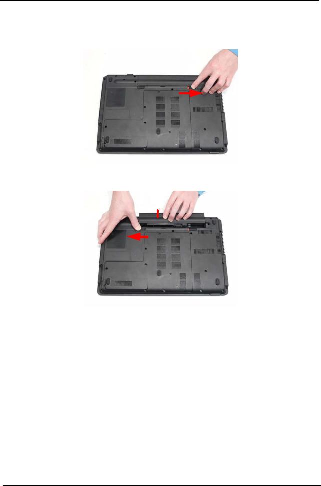
Removing the Battery Pack
1.Turn the computer over.
2.Slide the battery lock to the unlocked position.
3.Slide and hold the battery release latch to the release position (1), then lift out the battery pack from the main unit (2).
2 
1
42 |
Chapter 3 |
Downloaded from www.Manualslib.com manuals search engine
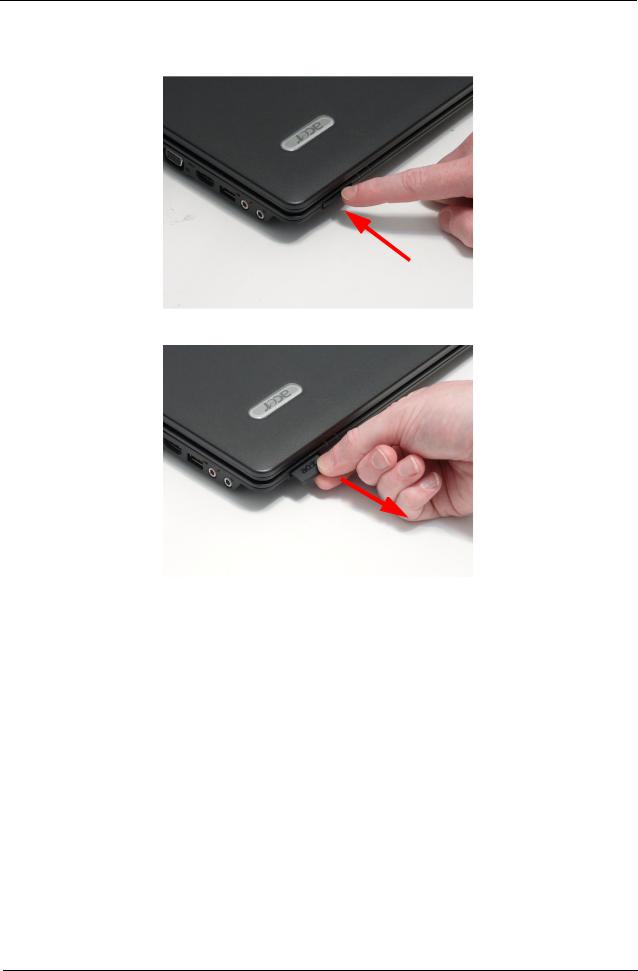
Removing the SD Dummy Card
1.Push the SD Dummy Card all the way in to eject it.
2.Pull the card out from the slot.
Chapter 3 |
43 |
Downloaded from www.Manualslib.com manuals search engine
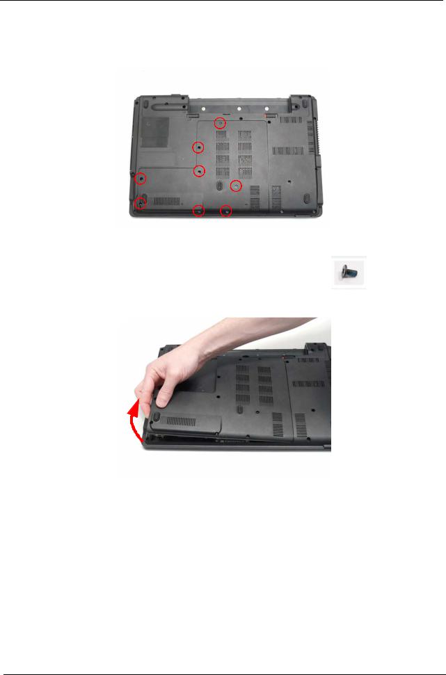
Removing the Lower Door
1.See “Removing the Battery Pack” on page 42.
2.Remove the eight screws securing the Lower Door to the Lower Cover.
Step |
|
Size |
Quantity |
Screw Type |
|
|
|
|
|
Lower Door |
M2.5*5 |
|
8 |
|
|
|
|
|
|
3.Remove the Lower Door as shown.
44 |
Chapter 3 |
Downloaded from www.Manualslib.com manuals search engine
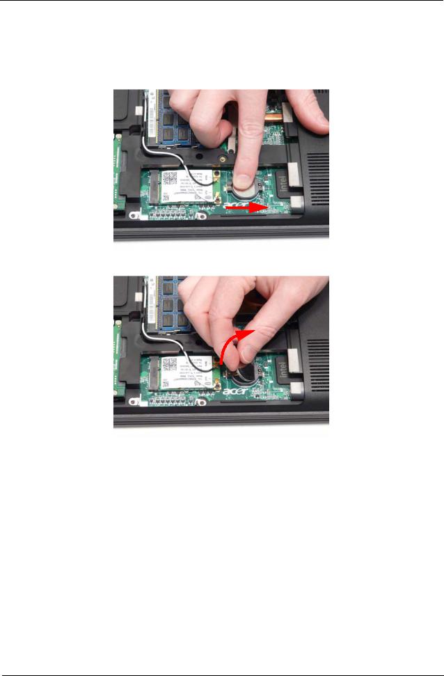
Removing the RTC Battery
IMPORTANT: Follow local regulations for disposal of all batteries.
1.See “Removing the Lower Door” on page 44.
IMPORTANT: Do not pry the battery out of the socket. Using force may permanently damage the battery socket.
2.Slide the RTC Battery to the right to release the securing clips in the battery socket.
3.Lift the battery clear of the socket.
Chapter 3 |
45 |
Downloaded from www.Manualslib.com manuals search engine
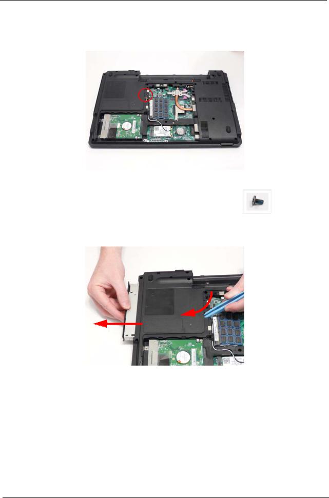
Removing the Optical Drive Module
1.See “Removing the Lower Door” on page 44.
2.Remove the single screw securing the ODD Module.
Step |
|
Size |
Quantity |
Screw Type |
|
|
|
|
|
ODD Module |
M2.5*5 |
|
1 |
|
|
|
|
|
|
3.Insert a suitable object in to the Lower Cover to push the ODD Module clear of the casing.
4.Pull the ODD Module out of the chassis.
46 |
Chapter 3 |
Downloaded from www.Manualslib.com manuals search engine
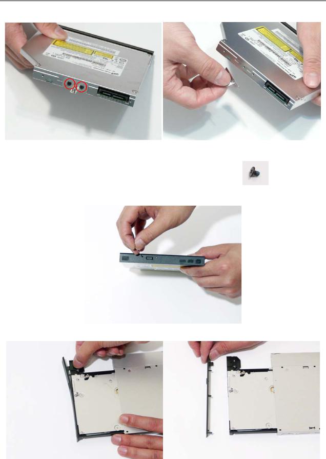
5.Remove the two screws securing the ODD Bracket and remove the ODD bracket from the module.
Step |
|
Size |
Quantity |
Screw Type |
|
|
|
|
|
ODD Bracket |
M2*3 |
|
2 |
|
|
|
|
|
|
6.Insert a pin in the eject hole of the ODD to eject the ODD tray.
7.Press down on the locking catch to release the ODD cover and remove.
|
|
|
|
|
|
|
|
Chapter 3 |
47 |
||
Downloaded from www.Manualslib.com manuals search engine
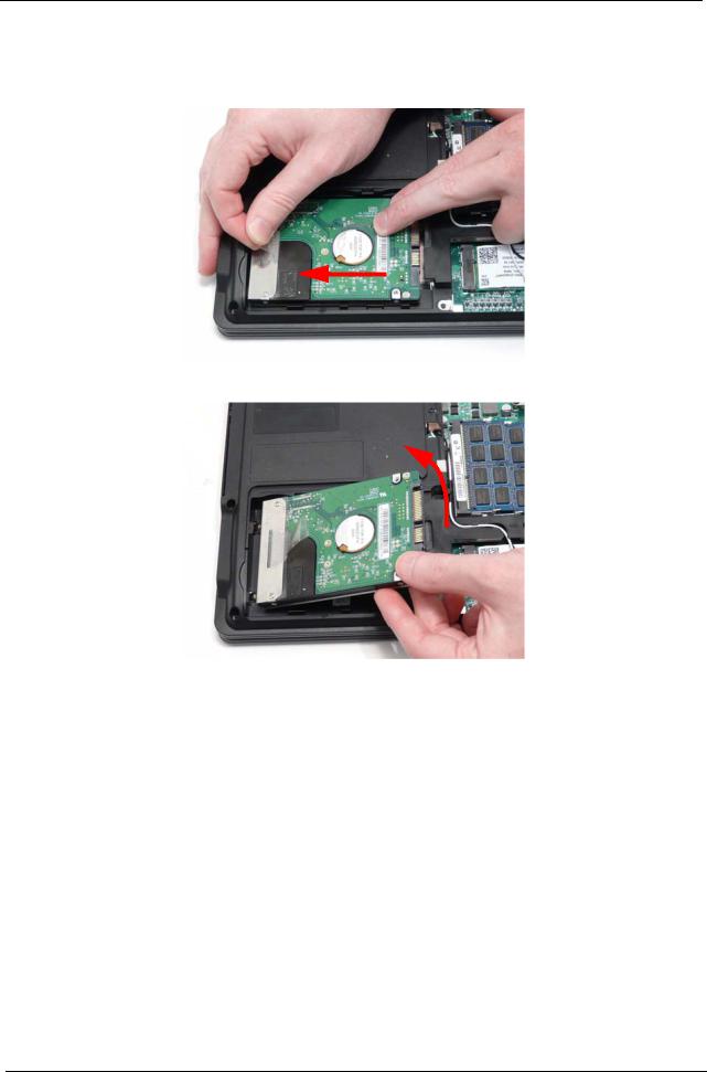
Removing the Hard Disk Drive Module
1.See “Removing the Lower Door” on page 44.
2.Use the pull-tab to slide the HDD in the indicated direction and disconnect the interface.
3.Lift the hard disk drive module out of the bay, right side first as shown.
NOTE: To prevent damage to device, avoid pressing down on it or placing heavy objects on top of it.
48 |
Chapter 3 |
Downloaded from www.Manualslib.com manuals search engine
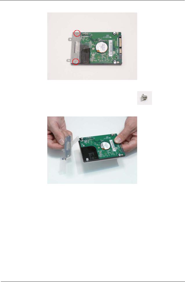
4.Remove the two screws securing the hard disk to the carrier.
Step |
|
Size |
Quantity |
Screw Type |
|
|
|
|
|
HDD Carrier |
M3*3 |
|
2 |
|
|
|
|
|
|
5.Remove the HDD from the carrier.
Chapter 3 |
49 |
Downloaded from www.Manualslib.com manuals search engine
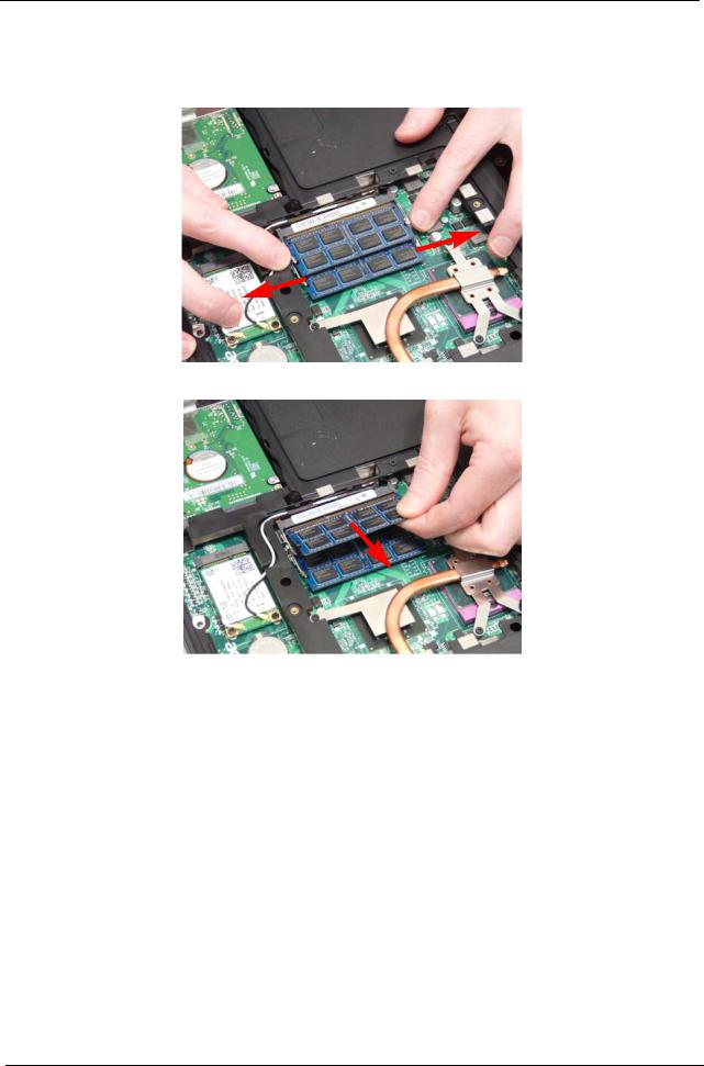
Removing the DIMM Modules
1.See “Removing the Lower Door” on page 44.
2.Push out the release latches on both sides of the DIMM socket to release the DIMM module.
3.Remove the DIMM module.
4.Repeat steps for the second DIMM module.
50 |
Chapter 3 |
Downloaded from www.Manualslib.com manuals search engine