

acer extensa 5635
.pdfChapter 5
Jumper and Connector Locations
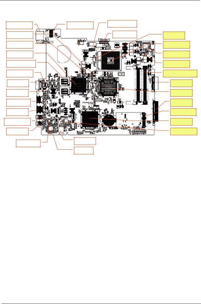
Top View
PU1/ SM BUS IC
CN1 LCD wire Conn
CN2/ K/B FFC conn.
U2 / LAN control IC
PU2 +1.5VSUS PWM
U4 LAN EEPROM IC
U5 / CPU thermal IC
CN4/ Int. SPK. Conn.
Glide PAD FFC Conn
PU5 Thermal protection
PU3 / Charge PWM IC
U7/U9 Dis VRAM
Y3/ KBC X’tal
U10 Fan control IC,
U14/ EC/ KBC
U11 HDMI lever shift
CN9/ BT wire
U13 Clock generator
U17 System BIOS
CN7 Card reader Conn
CN8 / Ext USB wire Conn
U16 Acer ID ROM
Glide PAD Left SW |
|
Glide PAD Right SW |
|
|
|
|
|
|
|
|
|
|
|
Y4 S.B X’tal. |
|
|
|
|
|
Chapter 5 |
111 |
Downloaded from www.Manualslib.com manuals search engine
Bottom View
|
|
|
|
|
|
|
|
|
|
|
|
PJ2/ PWR Jack conn. |
|
|
CN9 / LAN Conn |
|
|
|
U21 / LAN transformer |
|
|
||||||
|
|
|
|
|
|
|
|||||||
|
|
|
|
|
|
|
|
|
|
|
|
|
|
|
|
|
|
|
|
|
|
|
|
|
|||
|
|
|
|
|
|
|
|
|
PJ1 Battery Conn |
||||
|
U24 DIS HDCP ROM |
|
|
|
|
|
|
|
|||||
|
|
|
|
|
|
|
|
|
|
|
|||
|
|
|
|
|
|
|
|
|
|
||||
|
U23 Dis Spectrum IC |
|
|
|
|
|
|
|
|
||||
|
|
|
|
|
|
|
|
|
|
|
|||
|
|
|
|
|
|
|
|
|
|
|
|
|
|
|
U27 / N10 VGA IC |
|
|
|
|
|
|
|
|
||||
|
|
|
|
|
|
|
|
|
|
|
|
|
|
|
|
|
|
|
|
|
|
|
|
|
|
|
|
|
U25 / U27 Dis VRAM IC. |
|
|
|
|
|
|
|
|
||||
|
|
|
|
|
|
|
|
|
|
|
|
|
|
|
|
|
|
|
|
|
|
|
|
||||
|
U9 / CRT Switch IC |
|
|
|
|
|
|
|
|
||||
|
|
|
|
|
|
|
|
|
|
|
|
|
|
|
|
|
|
|
|
|
|
|
|
|
|
|
|
|
CN11 / CRT Conn |
|
|
|
|
|
|
|
|
|
|
||
|
|
|
|
|
|
|
|
|
|
|
|
|
|
|
|
|
|
|
|
|
|
|
|
|
|||
|
CN14 /FAN Conn |
|
|
|
|
|
|
|
|
|
|||
|
|
|
|
|
|
|
|
|
|
|
|
||
|
|
|
|
|
|
|
|
|
|
|
|
|
|
|
CN15 / HDMI Conn. |
|
|
|
|
|
|
|
|
|
|||
|
|
|
|
|
|
|
|
|
|
|
|
|
|
|
|
|
|
|
|
|
|
|
|
|
|||
|
CN16 / USB |
|
|
|
|
|
|
|
|
|
|||
|
|
|
|
|
|
|
|
|
|
|
|
||
|
|
|
|
|
|
|
|
|
|
|
|||
|
CN18 / EXT Mic conn |
|
|
|
|
|
|
|
|
|
|||
|
|
|
|
|
|
|
|
|
|
|
|
||
|
|
|
|
|
|
|
|
|
|
|
|||
|
CN21 / EXT HP |
|
|
|
|
|
|
|
|
|
|||
|
|
|
|
|
|
|
|
|
|
|
|
|
|
|
|
|
|
|
|
|
|
|
|
|
|
|
|
|
|
|
|
|
|
|
|
|
U18 Card reader |
|
|
|
|
|
|
U31 SPK Amplify IC |
|
|
|
|
|
||||||
|
|
|
|
|
|
|
|
|
|||||
|
|
|
|
|
|
|
|
|
|
|
|
|
|
|
|
|
|
|
|
|
|
|
U33 Codec IC |
|
|
|
|
|
|
|
|
|
|
|
|
|
|
|
|
|
|
PU8 VGA 1.1V
U22 / CPU socket
PU6/ CPU core
PU7/ +1.05V PWM
CN12, CN13 / Memory DIMM
CN10 ODD Conn
U28 N.B.
CN17 HDD Conn
CN19 Mini card Conn
U32 SB
PU10/ 3V/5V PWM IC
112 |
Chapter 5 |
Downloaded from www.Manualslib.com manuals search engine
Clearing Password Check and BIOS Recovery
This section provides you the standard operating procedures of clearing password and BIOS recovery for Extensa 5635/5635Z/5235. Extensa 5635/5635Z/5235 provides oneHardware Open Gap on main board for clearing password check, and one Hotkey for enabling BIOS Recovery.
Clearing Password Check
Hardware Open Gap Description
Steps for Clearing BIOS Password Check
If users set a BIOS Password (Supervisor Password and/or User Password) for security reasons, the BIOS will prompt for a password during system POST or when systems enter to BIOS Setup menu. However, if it is necessary to bypass the password check, users need to short the HW Gap to clear the password by performing the following procedure:
1.Power off the system, and unplug the AC and Battery from the machine.
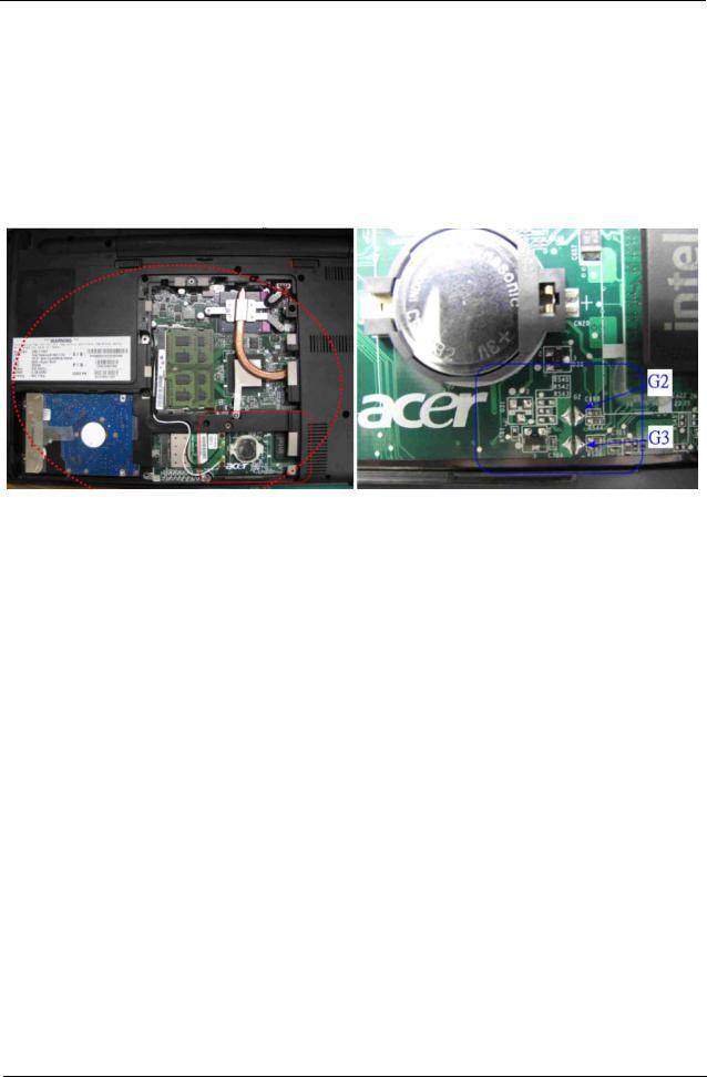
2.Open the Hard Drive and RAM door.
3.Find the appropriate HW Gap on M/B as shown in the picture.
•G2 is the Secondary RTC Reset. This signal resets the manageablility register bits in the RTC well when the TRTC battery is removed. The SRTCRST# input must always be high when all other RTC power planes are on. In the case where the RTC Battery is dead or missing on the platform, the SRTCRST# pin must rise before the RSMRST# pin.
•G3 is the RTC Reset. When asserted, this signal resets register bits in the RTC well. Unless the CMOS is being cleared (only to be done in the G3 power state), the RTCRST# input must always be high when all other RTC power planes are on. In the case where the RTC Battery is dead or missing on the platform, the RTCRST# pin must rise before the RSMRST# pin.
4.Use an electric conductivity tool to short the two points of the HW Gap G3.
5.Plug in AC, keeping the HW Gap shorted, and press Power Button to power on the system till BIOS POST finish. Then remove the tool from the HW Gap.
6.Restart system. Press F2 key to enter BIOS Setup menu.
If there is no Password request, the BIOS Password has been successfully cleared. Otherwise, please follow the steps and try again.
NOTE: The steps are only for clearing BIOS Password (Supervisor Password and User Password).
Chapter 5 |
113 |
Downloaded from www.Manualslib.com manuals search engine

BIOS Recovery by Crisis Disk
BIOS Recovery Boot Block:
BIOS Recovery Boot Block is a special block of BIOS. It is used to boot up the system with minimum BIOS initialization. Users can enable this feature to restore the BIOS firmware to a successful one if a previous BIOS flashing process fails.
BIOS Recovery Hotkey:
The system provides a function hotkey: Fn+Esc, for enabling BIOS Recovery process when the system is powered on during BIOS POST. To use this function, it is strongly recommended to have the AC adapter and Battery present. If this function is enabled, the system will force the BIOS to enter a special BIOS block, called Boot Block.
Steps for BIOS Recovery from USB Storage:
Before doing this, prepare the Crisis USB key. The Crisis USB key can be made by executing the Crisis Disk program in another system with Windows XP OS.
Follow the steps below:
1.Save the ROM file along with Flashit.exe (BIOS flash tool) to the root directory of the USB storage disk.
2.Plug USB storage disk into the USB port.
3.Press Fn + ESC + Power buttons. Remove your finger from the Power button but keep the Fn + Esc keys pressed till the Power button flashes once.
Note: During the first iteration, the LED of the USB disk will keep flashing forabout 3 - 7 minutes. After this, the system restarts. You can check the BIOS version after the system restarts. If correct, the crisis system is set up correctly.
114 |
Chapter 5 |
Downloaded from www.Manualslib.com manuals search engine

Chapter 6
FRU (Field Replaceable Unit) List
This chapter gives you the FRU (Field Replaceable Unit) listing in global configurations of Extensa 5635/ 5635Z/5235. Refer to this chapter whenever ordering for parts to repair or for RMA (Return Merchandise Authorization).
Please note that WHEN ORDERING FRU PARTS, you shou ld check the most up-to-date information available on your regional web or channel. For whatever reasons a part number change is made, it will not be noted on the printed Service Guide. For ACER AUTHORIZED SERVICE PROVIDERS, your Acer office may have a DIFFERENT part number code from those given in the FRU list of this printed Service Guide. You MUST use the local FRU list provided by your regional Acer office to order FRU parts for repair and service of customer machines.
NOTE: To scrap or to return the defective parts, you should follow the local government ordinance or regulations on how to dispose it properly, or follow the rules set by your regional Acer office on how to return it.
Chapter 6 |
115 |
Downloaded from www.Manualslib.com manuals search engine
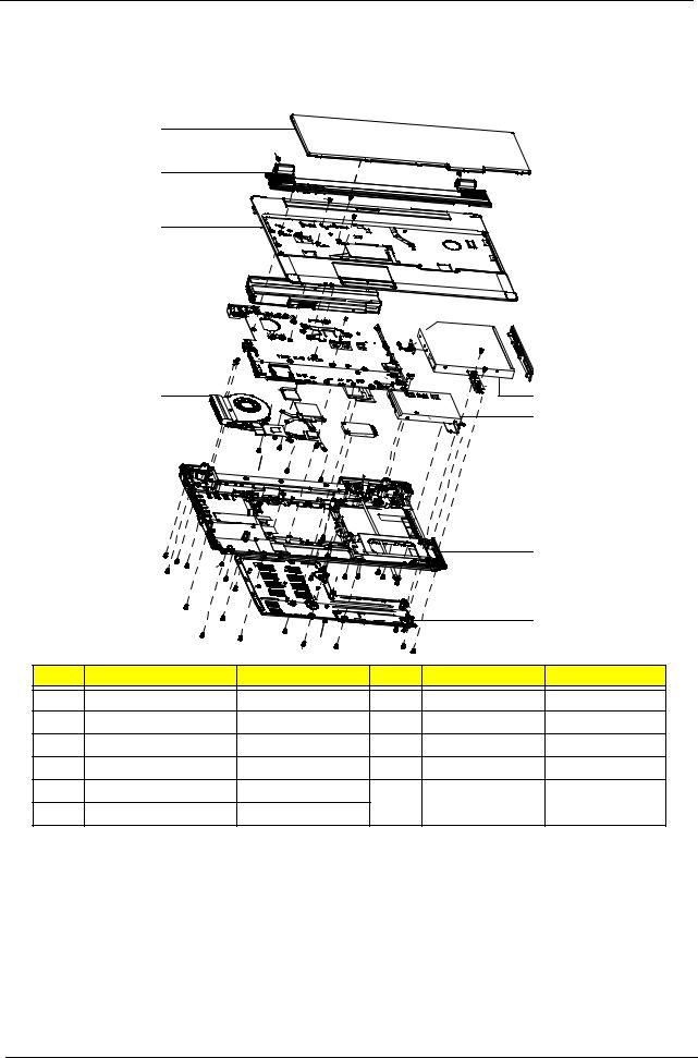
Extensa 5635/5635Z/5235 Exploded Diagrams
Main Assembly
1
2
3
4
5
 7
7
6 |
8 |
|
9 |
|
|
|
|
|
10 |
|
|
|
|
|
11 |
Item |
Description |
Part Number |
Item |
Description |
Part Number |
1 |
Keyboard |
KB.INT00.105 |
7 |
ODD Bezel |
42.EDM07.003 |
2 |
Switch Cover |
42.EDW07.001 |
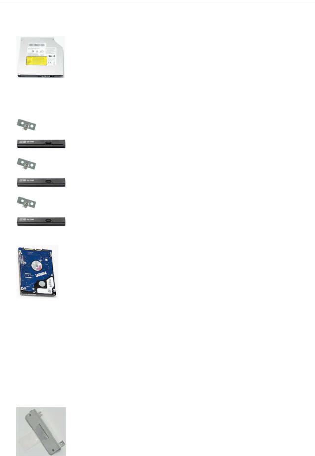
8 |
ODD Module |
6M.EDM07.001 |
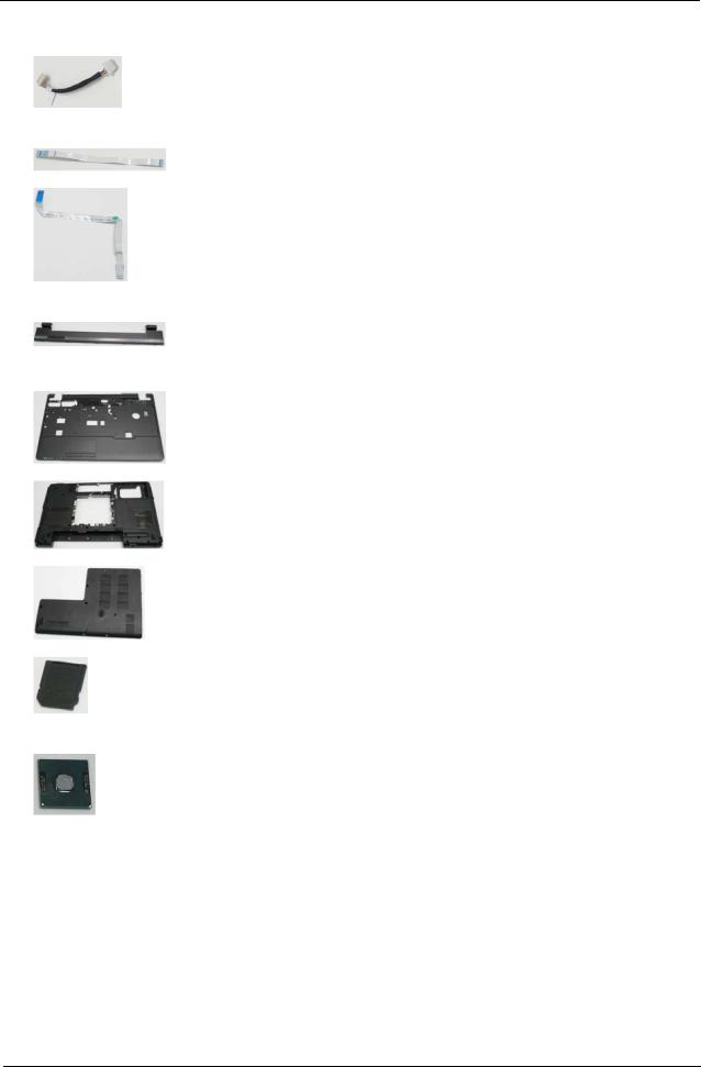
3 |
Upper Cover |
60.EDM07.001 |
9 |
HDD |
KH.16004.006 |
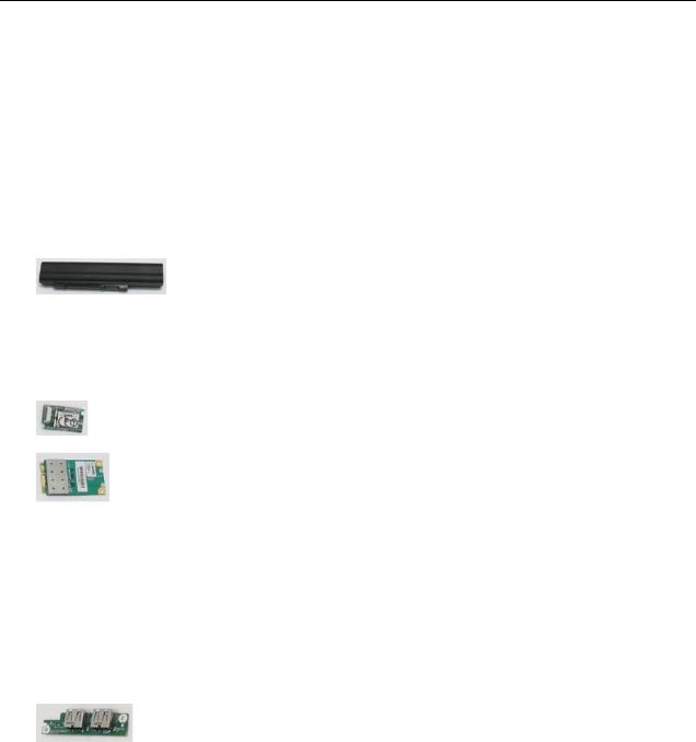
4 |
Battery |
BT.00607.072 |
10 |
Lower Cover |
60.EDM07.002 |
5 |
Mainboard |
MB.EDX06.001 |
11 |
Lower Door |
42.EDM07.002 |
6 |
Thermal Module |
60.EDR07.002 |
|
|
|
116 |
Chapter 6 |
Downloaded from www.Manualslib.com manuals search engine
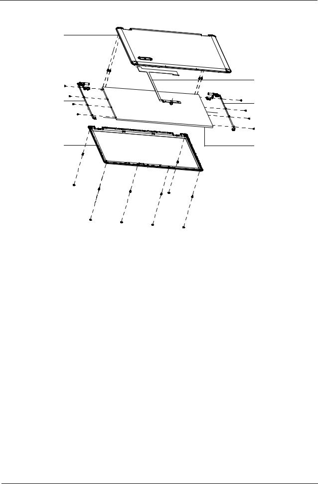
LCD Assembly
1
4
2 |
5 |
3 |
6 |
Item |
Description |
Part Number |
|
|
|
1 |
LCD Cover |
60.EDM07.003 |
|
|
|
2 |
LCD Bracket_L |
33.EDM07.003 |
|
|
|
3 |
LCD Bezel |
60.EDR07.001 |
|
|
|
4 |
LCD Cable |
50.EDM07.005 |
|
|
|
5 |
LCD Bracket_R |
33.EDM07.002 |
|
|
|
6 |
LCD Panel |
LK.15605.003 |
|
|
|
Chapter 6 |
117 |
Downloaded from www.Manualslib.com manuals search engine
Extensa 5635/5635Z/5235 FRU List
|
|
CATEGORY |
PARTNAME |
ACER P/N |
|
|
|
|
|
|
|
|
|
Adapter |
|
|
|
|
|
|
Adapter DELTA 65W 19V 1.7x5.5x11 Yellow ADP-65JH |
AP.06501.026 |
|
|
|
|
DB A, LV5 LED LF |
|
|
|
|
|
|
|
|
|
|
|
Adapter LITE-ON 65W 19V 1.7x5.5x11 Yellow PA-1650- |
AP.06503.024 |
|
|
|
|
22AC LV5 LED LF |
|
|
|
|
|
|
|
|
|
|
|
Adapter HIPRO 65W 19V 1.7x5.5x11 Yellow HP- |
AP.0650A.012 |
|
|
|
|
A0652R3B 1LF, LV5 LED LF |
|
|
|
|
|
|
|
|
|
|
Battery |
|
|
|
|
|
|
|
|
|
|
|
|
Battery SIMPLO AS-2009C Li-Ion 3S2P PANASONIC 6 |
BT.00607.072 |
|
|
|
|
cell 4400mAh Main COMMON |
|
|
|
|
|
|
|
|
|
|
|
Battery SIMPLO AS-2009C Li-Ion 3S2P SAMSUNG 6 |
BT.00607.073 |
|
|
|
|
cell 4400mAh Main COMMON |
|
|
|
|
|
|
|
|
|
|
|
Battery SANYO AS-2009C Li-Ion 3S2P SANYO 6 cell |
BT.00603.078 |
|
|
|
|
4400mAh Main COMMON |
|
|
|
|
|
|
|
|
|
|
Board |
|
|
|
|
|
|
|
|
|
|
|
|
BLUETOOTH MODULE (T60H928.11) |
BT.21100.005 |
|
|
|
|
|
|
|
|
|
|
Foxconn Wireless LAN Atheros AR5B91 1x2 BGN |
NI.23600.030 |
|
|
|
|
|
|
|
|
|
|
WIRELESS LAN CARD FOXCONN T60h976.00 MINI |
54.AZL07.001 |
|
|
|
|
|
|
|
|
|
|
QMI WIRELESS LAN ATHEROS AR5B91 1X2 BGN |
NI.23600.033 |
|
|
|
|
|
|
|
|
|
|
QMI Wireless LAN Atheros HB95 (HM) EM305 |
NI.23600.050 |
|
|
|
|
|
|
|
|
|
|
Foxconn Wireless LAN Wireless LAN Ralink RT2700E |
NI.23600.031 |
|
|
|
|
1x2 BGN |
|
|
|
|
|
|
|
|
|
|
|
Lan Intel WLAN 512AG_MMWG Shirley Peak 5100 |
KI.SPM01.005 |
|
|
|
|
MM#897004 |
|
|
|
|
|
|
|
|
|
|
|
Lan Intel WLAN 512AN_MMWG2 Shirley Peak 5100 ME |
KI.SPM01.008 |
|
|
|
|
enable / MM#899541 |
|
|
|
|
|
|
|
|
|
|
|
Lan Intel WLAN 512AN_MMWG Shirley Peak 5100 |
KI.SPM01.003 |
|
|
|
|
MM#895361 TA#E14718-014 |
|
|
|
|
|
|
|
|
|
|
|
USB BOARD |
55.EDM07.001 |
|
|
|
|
|
|
|
|
|
Cable |
|
|
|
|
|
|
|
|
|
|
|
|
PWR CORD V943B30001218008 DANISH 3P |
27.A03V7.006 |
|
|
|
|
|
|
|
|
|
|
PWR CORD(ISR)1.8M 3PBLK FZ0I0008-038 |
27.TATV7.005 |
|
|
|
|
|
|
|
|
|
|
PWR CORD V50CB3T3012180QD TW-110V,3P |
27.A99V7.002 |
|
|
|
|
|
|
|
|
|
|
POWER CORD(SWI)1.8M 3PBLACK FZ010008-011 |
27.A99V7.004 |
|
|
|
|
|
|
|
|
|
|
POWER CORD(IT) 1.8M 3PBLACK FZ010008-008 |
27.A99V7.005 |
|
|
|
|
|
|
|
|
|
|
POWER CORD(S.A) 1.8M 3BLACK FZ010008-006 |
27.T48V7.001 |
|
|
|
|
|
|
|
|
|
|
POWER CORD US 3PIN ROHS |
27.TAXV7.001 |
|
|
|
|
|
|
|
|
|
|
POWER CORD(EU) 1.8M 3PBLACK FM010008-010 |
27.TATV7.001 |
|
|
|
|
|
|
|
|
|
|
POWER CORD(UK) 1.8M 3PBLACK FP010008-013 |
27.TATV7.003 |
|
|
|
|
|
|
|
|
|
|
POWER CORD BRAZIL IMETRO 3 PIN |
27.S0607.001 |
|
|
|
|
|
|
|
|
|
|
POWER CORD(S.A) 1.8M 3BLACK FZ010008-006 |
27.T48V7.001 |
|
|
|
|
|
|
|
|
|
|
|
|
|
118 |
|
|
Chapter 6 |
||
Downloaded from www.Manualslib.com manuals search engine
CATEGORY |
PARTNAME |
ACER P/N |
|
|
|
|
BLUETOOTH CABLE |
50.EDM07.001 |
|
|
|
|
DC IN CABLE |
50.EDM07.002 |
|
|
|
|
FFC CABLE - USB/B TO NB |
50.EDM07.003 |
|
|
|
|
FFC CABLE - TP TO NB |
50.EDM07.004 |
|
|
|
Case/Cover/Bracket Assembly |
|
|
|
MIDDLE COVER FOR EX5635 |
42.EDW07.001 |
|
|
|
|
MIDDLE COVER FOR EX5635Z |
42.EDM07.001 |
|
|
|
|
MIDDLE COVER FOR EX5235 |
42.EDP07.001 |
|
|
|
|
UPPER CASE ASSY W/TP,SPEAKER,MIC |
60.EDM07.001 |
|
|
|
|
LOWER CASE ASSY W/DC-IN CABLE, USB FFC |
60.EDM07.002 |
|
|
|
|
BASE COVER W/RUBBER |
42.EDM07.002 |
|
|
|
|
SD DUMMY CARD |
42.S6507.003 |
|
|
|
CPU/Processor |
|
|
|
|
|
|
CPU Intel CeleronM T1600 1.66G 1M 667 Dual Core, |
KC.16001.CMT |
|
MV |
|
|
|
|
|
CPU Intel Core2Dual P7370 PGA 2.0G 3M 1066 25W |
KC.73701.DPP |
|
|
|
|
CPU Intel Pentium Dual-Core T4200 PGA 2.0G 1M 800 |
KC.42001.DTP |
|
35W R-0 no VT |
|
|
|
|
|
CPU Intel Core2Dual T6570 PGA 2.1G 2M 800 R-0 |
KC.65701.DTP |
|
|
|
|
CPU Intel Core2Dual T6600 PGA 2.2G 2M 800 35W R-0 |
KC.66001.DTP |
|
|
|
Chapter 6 |
119 |
Downloaded from www.Manualslib.com manuals search engine
|
|
CATEGORY |
PARTNAME |
ACER P/N |
|
|
|
|
|
|
|
|
|
ODD |
|
|
|
|
|
|
DVD/RW SUPER MULTI SATA MODULE |
6M.EDM07.001 |
|
|
|
|
|
|
|
|
|
|
ODD PANASONIC Super-Multi DRIVE 12.7mm Tray DL |
KU.00807.064 |
|
|
|
|
8X UJ880A LF W/O bezel SATA |
|
|
|
|
|
|
|
|
|
|
|
ODD TOSHIBA Super-Multi DRIVE 12.7mm Tray DL 8X |
KU.00801.030 |
|
|
|
|
TS-L633B LF W/O bezel SATA |
|
|
|
|
|
|
|
|
|
|
|
SUPER-MULTI DRIVE 12.7MM SONY TRAY DL 8X AD- |
KU.0080E.017 |
|
|
|
|
7580S LF W/O BEZEL SATA |
|
|
|
|
|
|
|
|
|
|
|
ODD PLDS Super-Multi DRIVE 12.7mm Tray DL 8X DS- |
KU.0080F.004 |
|
|
|
|
8A3S LF W/O bezel SATA |
|
|
|
|
|
|
|
|
|
|
|
ODD BRACKET |
33.PDA07.003 |
|
|
|
|
|
|
|
|
|
|
ODD BEZEL - SUPER MULTI |
42.EDM07.003 |
|
|
|
|
|
|
|
|
|
|
ODD BRACKET |
33.PDA07.003 |
|
|
|
|
|
|
|
|
|
|
BD COMBO BEZEL |
42.EDM07.004 |
|
|
|
|
|
|
|
|
|
|
ODD BRACKET |
33.PDA07.003 |
|
|
|
|
|
|
|
|
|
|
DVD/CDRW COMBO BEZEL |
42.EDM07.005 |
|
|
|
|
|
|
|
|
|
HDD |
|
|
|
|
|
|
|
|
|
|
|
|
HDD TOSHIBA 2.5" 5400rpm 160GB MK1655GSX Libra |
KH.16004.006 |
|
|
|
|
SATA LF F/W: FG011J |
|
|
|
|
|
|
|
|
|
|
|
HDD HGST 2.5" 5400rpm 250GB HTS545025B9A300 |
KH.25007.015 |
|
|
|
|
Panther B SATA LF F/W:C50K |
|
|
|
|
|
|
|
|
|
|
|
HDD TOSHIBA 2.5" 5400rpm 320GB MK3255GSX Libra |
KH.32004.002 |
|
|
|
|
SATA LF F/W:FG011J |
|
|
|
|
|
|
|
|
|
|
|
HDD HGST 2.5" 5400rpm 500GB HTS545050B9A300 |
KH.50007.009 |
|
|
|
|
Panther B SATA LF F/W:C60F |
|
|
|
|
|
|
|
|
|
|
|
HDD SEAGATE 2.5" 5400rpm 250GB ST9250315AS |
KH.25001.016 |
|
|
|
|
Wyatt SATA LF F/W:0001SDM1 |
|
|
|
|
|
|
|
|
|
|
|
HDD TOSHIBA 2.5" 5400rpm 250GB MK2555GSX Libra |
KH.25004.003 |
|
|
|
|
SATA LF F/W:FG001J |
|
|
|
|
|
|
|
|
|
|
|
HDD HGST 2.5" 5400rpm 320GB HTS545032B9A300 |
KH.32007.007 |
|
|
|
|
Panther B SATA LF F/W: C60F |
|
|
|
|
|
|
|
|
|
|
|
HDD WD 2.5" 5400rpm 320GB WD3200BEVT-22ZCT0 |
KH.32008.013 |
|
|
|
|
ML160 SATA LF F/W:11.01A11 |
|
|
|
|
|
|
|
|
|
|
|
HDD WD 2.5" 5400rpm 500GB WD5000BEVT-22ZAT0 |
KH.50008.013 |
|
|
|
|
ML250 SATA LF F/W:01.01A01 |
|
|
|
|
|
|
|
|
|
|
|
HDD BRACKET |
33.EDM07.001 |
|
|
|
|
|
|
|
|
|
|
|
|
|
120 |
|
Chapter 6 |
|||
Downloaded from www.Manualslib.com manuals search engine