

acer extensa 5635
.pdfInternal Microphone Failure
If the internal Microphone fails, perform the following actions one at a time to correct the problem. Do not replace a non-defective FRUs:
Microphone Problems
If internal or external Microphones do no operate correctly, perform the following actions one at a time to correct the problem.
1.Check that the microphone is enabled. Navigate to Start´ Control Panel´ Hardware and Sound´ Sound and select the Recording tab.
2.Right-click on the Recording tab and select Show Disabled Devices (clear by default).
3.The microphone appears on the Recording tab.
4.Right-click on the microphone and select Enable.
5.Select the microphone then click Properties. Select the Levels tab.
6.Increase the volume to the maximum setting and click OK.
7.Test the microphone hardware:
a.Select the microphone and click Configure.
b.Select Set up microphone.
c.Select the microphone type from the list and click Next.
d.Follow the onscreen prompts to complete the test.
8.If the Issue is still not resolved, see “Online Support Information” on page 185.
Chapter 4 |
101 |
Downloaded from www.Manualslib.com manuals search engine

HDD Not Operating Correctly
If the HDD does not operate correctly, perform the following actions one at a time to correct the problem.
1.Disconnect all external devices.
2.Run a complete virus scan using up-to-date software to ensure the computer is virus free.
3.Run the Windows Vista Startup Repair Utility:
a.insert the Windows Vista Operating System DVD in the ODD and restart the computer.
b.When prompted, press any key to start to the operating system DVD.
c.The Install Windows screen displays. ClickNext.
d.Select Repair your computer.
e.The System Recovery Options screen displays. Click Next.
f.Select the appropriate operating system, and click Next.
NOTE: Click Load Drivers if controller drives are required.
g.Select Startup Repair.
h.Startup Repair attempts to locate and resolve issues with the computer.
i.When complete, click Finish.
If an issue is discovered, follow the onscreen information to resolve the problem.
4.Run the Windows Memory Diagnostic Tool. For more information see Windows Help and Support.
5.Restart the computer and press F2 to enter the BIOS Utility. Check the BIOS settings are correct and that CD/DVD drive is set as the first boot device on the Boot menu.
6.Ensure all cables and jumpers on the HDD and ODD are set correctly.
7.Remove any recently added hardware and associated software.
8.Run the Windows Disk Defragmenter. For more information see Windows Help and Support.
9.Run Windows Check Disk by entering chkdsk /r from a command prompt. For more information see Windows Help and Support.
10.Restore system and file settings from a known good date using System Restore.
If the issue is not fixed, repeat the preceding steps and select an earlier time and date.
11.Replace the HDD. See “Disassembly Process” on page 40.
102 |
Chapter 4 |
Downloaded from www.Manualslib.com manuals search engine
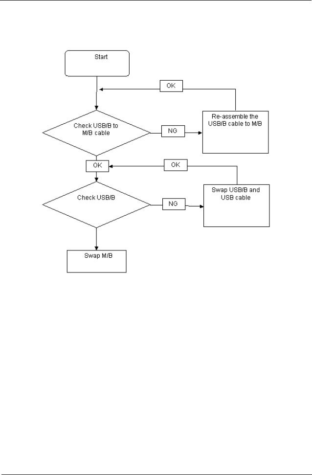
USB Failure (Rightside)
If the rightside USB port fails, perform the following actions one at a time to correct the problem. Do not replace a non-defective FRUs:
Chapter 4 |
103 |
Downloaded from www.Manualslib.com manuals search engine

External Mouse Failure
If an external Mouse fails, perform the following actions one at a time to correct the problem.
1.Try an alternative mouse.
2.If the mouse uses a wireless connection, insert new batteries and confirm there is a good connection. See the mouse user manual.
3.If the mouse uses a USB connection, try an alternate USB port.
4.Try an alternative program to verify mouse operation. Reinstall the program experiencing mouse failure.
5.Restart the computer.
6.Remove any recently added hardware and associated software.
7.Remove any recently added software and reboot.
8.Restore system and file settings from a known good date using System Restore.
If the issue is not fixed, repeat the preceding steps and select an earlier time and date.
9.Run the Event Viewer to check the events log for errors. For more informat ion see Windows Help and Support.
10.Roll back the mouse driver to the previous version if updated recently.
11.Remove and reinstall the mouse driver.
12.Check the Device Manager to determine that:
•The device is properly installed. There are no red Xs or yellow exclamation marks.
•There are no device conflicts.
•No hardware is listed under Other Devices.
13.If the Issue is still not resolved, see “Online Support Information” on page 185.
104 |
Chapter 4 |
Downloaded from www.Manualslib.com manuals search engine

Other Failures
If the CRT Switch, Dock, LAN Port, external MIC or Speakers, PCI Express Card, 5-in-1 Card Reader or Volume Wheel fail, perform the following general steps to correct the problem. Do not replace a non-defective FRUs:
1.Check Drive whether is OK.
2.Check Test Fixture is ok.
3.Swap M/B to Try.
Intermittent Problems
Intermittent system hang problems can be caused by a variety of reasons that have nothing to do with a hardware defect, such as: cosmic radiation, electrostatic discharge, or software errors. FRU replacement should be considered only when a recurring problem exists.
When analyzing an intermittent problem, do the following:
1.Run the advanced diagnostic test for the system board in loop mode at least 10 times.
2.If no error is detected, do not replace any FRU.
3.If any error is detected, replace the FRU. Rerun the test to verify that there are no more errors.
Undetermined Problems
The diagnostic problems does not identify which adapter or device failed, which installed devices are incorrect, whether a short circuit is suspected, or whether the system is inoperative.
Follow these procedures to isolate the failing FRU (do not isolate non-defective FRU). NOTE: Verify that all attached devices are supported by the computer.
NOTE: Verify that the power supply being used at the time of the failure is operating correctly. (See “Power On Issue” on page 92):
1.Power-off the computer.
2.Visually check them for damage. If any problems are found, replace the FRU.
3.Remove or disconnect all of the following devices:
•Non-Acer devices
•Printer, mouse, and other external devices
•Battery pack
•Hard disk drive
•DIMM
•CD-ROM/Diskette drive Module
•PC Cards
4.Power-on the computer.
5.Determine if the problem has changed.
6.If the problem does not recur, reconnect the removed devices one at a time until you find the failing FRU.
7.If the problem remains, replace the following FRU one at a time. Do not replace a non-defective FRU:
•System board
•LCD assembly
Chapter 4 |
105 |
Downloaded from www.Manualslib.com manuals search engine

POST Code Reference Tables
These tables describe the POST codes and components of the POST process.
Chipset POST Codes
The following table details the chipset POST codes and functions used in the POST.
|
|
Code |
Beeps |
POST Routine Description |
|
|
|
|
|
|
|
|
|
02h |
|
Verify Real Mode |
|
|
|
|
|
|
|
|
|
03h |
|
Disable Non-Maskable Interrupt (NMI) |
|
|
|
|
|
|
|
|
|
04h |
|
Get CPU type |
|
|
|
|
|
|
|
|
|
06h |
|
Initialize system hardware |
|
|
|
|
|
|
|
|
|
08h |
|
Initialize chipset with initial POST values |
|
|
|
|
|
|
|
|
|
09h |
|
Set IN POST flag |
|
|
|
|
|
|
|
|
|
0Ah |
|
Initialize CPU registers |
|
|
|
|
|
|
|
|
|
0Bh |
|
Enable CPU cache |
|
|
|
|
|
|
|
|
|
0Ch |
|
Initialize caches to initial POST values |
|
|
|
|
|
|
|
|
|
0Eh |
|
Initialize I/O component |
|
|
|
|
|
|
|
|
|
0Fh |
|
Initialize the local bus IDE |
|
|
|
|
|
|
|
|
|
10h |
|
Initialize Power Management |
|
|
|
|
|
|
|
|
|
11h |
|
Load alternate registers with initial POST values |
|
|
|
|
|
|
|
|
|
12h |
|
Restore CPU control word during warm boot |
|
|
|
|
|
|
|
|
|
13h |
|
Initialize PCI Bus Mastering devices |
|
|
|
|
|
|
|
|
|
14h |
|
Initialize keyboard controller |
|
|
|
|
|
|
|
|
|
16h |
1-2-2-3 |
BIOS ROM checksum |
|
|
|
|
|
|
|
|
|
17h |
|
Initialize cache before memory autosize |
|
|
|
|
|
|
|
|
|
18h |
8254 |
timer initialization |
|
|
|
|
|
|
|
|
|
1Ah |
8237 |
DMA controller initialization |
|
|
|
|
|
|
|
|
|
1Ch |
|
Reset Programmable Interrupt Controller |
|
|
|
|
|
|
|
|
|
20h |
1-3-1-1 |
Test DRAM refresh |
|
|
|
|
|
|
|
|
|
22h |
1-3-1-3 |
Test 8742 Keyboard Controller |
|
|
|
|
|
|
|
|
|
24h |
|
Set ES segment register to 4 GB |
|
|
|
|
|
|
|
|
|
26h |
|
Enable A20 line |
|
|
|
|
|
|
|
|
|
28h |
|
Autosize DRAM |
|
|
|
|
|
|
|
|
|
29h |
|
Initialize POST Memory Manager |
|
|
|
|
|
|
|
|
|
2Ah |
|
Clear 512 KB base RAM |
|
|
|
|
|
|
|
|
|
2Ch |
1-3-4-1 |
RAM failure on address line xxxx* |
|
|
|
|
|
|
|
|
|
2Eh |
1-3-4-3 |
RAM failure on data bits xxxx* of low byte of memory bus |
|
|
|
|
|
|
|
|
|
2Fh |
|
Enable cache before system BIOS shadow |
|
|
|
|
|
|
|
|
|
30h |
1-4-1-1 |
RAM failure on data bits xxxx* of high byte of memory bus |
|
|
|
|
|
|
|
|
|
32h |
|
Test CPU bus-clock frequency |
|
|
|
|
|
|
|
|
|
33h |
|
Initialize Phoenix Dispatch Manager |
|
|
|
|
|
|
|
|
|
36h |
|
Warm start shut down |
|
|
|
|
|
|
|
|
|
38h |
|
Shadow system BIOS ROM |
|
|
|
|
|
|
|
|
|
3Ah |
|
Autosize cache |
|
|
|
|
|
|
|
|
|
|
|
|
|
106 |
|
Chapter 4 |
|||
Downloaded from www.Manualslib.com manuals search engine

|
|
Code |
Beeps |
POST Routine Description |
|
|
|
|
|
|
|
|
|
3Ch |
|
Advanced configuration of chipset registers |
|
|
|
|
|
|
|
|
|
3Dh |
|
Load alternate registers with CMOS values |
|
|
|
|
|
|
|
|
|
42h |
|
Initialize interrupt vectors |
|
|
|
|
|
|
|
|
|
45h |
|
POST device initialization |
|
|
|
|
|
|
|
|
|
46h |
2-1-2-3 |
Check ROM copyright notice |
|
|
|
|
|
|
|
|
|
48h |
|
Check video configuration against CMOS |
|
|
|
|
|
|
|
|
|
49h |
|
Initialize PCI bus and devices |
|
|
|
|
|
|
|
|
|
4Ah |
|
Initialize all video adapters in system |
|
|
|
|
|
|
|
|
|
4Bh |
|
QuietBoot start (optional) |
|
|
|
|
|
|
|
|
|
4Ch |
|
Shadow video BIOS ROM |
|
|
|
|
|
|
|
|
|
4Eh |
|
Display BIOS copyright notice |
|
|
|
|
|
|
|
|
|
50h |
|
Display CPU type and speed |
|
|
|
|
|
|
|
|
|
51h |
|
Initialize EISA board |
|
|
|
|
|
|
|
|
|
52h |
|
Test keyboard |
|
|
|
|
|
|
|
|
|
54h |
|
Set key click if enabled |
|
|
|
|
|
|
|
|
|
58h |
2-2-3-1 |
Test for unexpected interrupts |
|
|
|
|
|
|
|
|
|
59h |
|
Initialize POST display service |
|
|
|
|
|
|
|
|
|
5Ah |
|
Display prompt Press F2 to enter SETUP |
|
|
|
|
|
|
|
|
|
5Bh |
|
Disable CPU cache |
|
|
|
|
|
|
|
|
|
5Ch |
|
Test RAM between 512 and 640 KB |
|
|
|
|
|
|
|
|
|
60h |
|
Test extended memory |
|
|
|
|
|
|
|
|
|
62h |
|
Test extended memory address lines |
|
|
|
|
|
|
|
|
|
64h |
|
Jump to UserPatch1 |
|
|
|
|
|
|
|
|
|
66h |
|
Configure advanced cache registers |
|
|
|
|
|
|
|
|
|
67h |
|
Initialize Multi Processor APIC |
|
|
|
|
|
|
|
|
|
68h |
|
Enable external and CPU caches |
|
|
|
|
|
|
|
|
|
69h |
|
Setup System Management Mode (SMM) area |
|
|
|
|
|
|
|
|
|
6Ah |
|
Display external L2 cache size |
|
|
|
|
|
|
|
|
|
6Bh |
|
Load custom defaults (optional) |
|
|
|
|
|
|
|
|
|
6Ch |
|
Display shadow-area message |
|
|
|
|
|
|
|
|
|
6Eh |
|
Display possible high address for UMB recovery |
|
|
|
|
|
|
|
|
|
70h |
|
Display error messages |
|
|
|
|
|
|
|
|
|
72h |
|
Check for configuration errors |
|
|
|
|
|
|
|
|
|
76h |
|
Check for keyboard errors |
|
|
|
|
|
|
|
|
|
7Ch |
|
Set up hardware interrupt vectors |
|
|
|
|
|
|
|
|
|
7Eh |
|
Initialize coprocessor if present |
|
|
|
|
|
|
|
|
|
80h |
|
Disable onboard Super I/O ports and IRQs |
|
|
|
|
|
|
|
|
|
81h |
|
Late POST device initialization |
|
|
|
|
|
|
|
|
|
82h |
|
Detect and install external RS232 ports |
|
|
|
|
|
|
|
|
|
83h |
|
Configure non-MCD IDE controllers |
|
|
|
|
|
|
|
|
|
84h |
|
Detect and install external parallel ports |
|
|
|
|
|
|
|
|
|
85h |
|
Initialize PC-compatible PnP ISA devices |
|
|
|
|
|
|
|
|
|
86h |
|
Re-initialize onboard I/O ports. |
|
|
|
|
|
|
|
|
|
|
|
|
|
Chapter 4 |
|
107 |
|||
Downloaded from www.Manualslib.com manuals search engine

|
|
Code |
Beeps |
POST Routine Description |
|
|
|
|
|
|
|
|
|
87h |
|
Configure Motherboard Configurable Devices (optional) |
|
|
|
|
|
|
|
|
|
88h |
|
Initialize BIOS Data Area |
|
|
|
|
|
|
|
|
|
89h |
|
Enable Non-Maskable Interrupts (NMIs) |
|
|
|
|
|
|
|
|
|
8Ah |
|
Initialize Extended BIOS Data Area |
|
|
|
|
|
|
|
|
|
8Bh |
|
Test and initialize PS/2 mouse |
|
|
|
|
|
|
|
|
|
8Ch |
|
Initialize floppy controller |
|
|
|
|
|
|
|
|
|
8Fh |
|
Determine number of ATA drives (optional) |
|
|
|
|
|
|
|
|
|
90h |
|
Initialize hard-disk controllers |
|
|
|
|
|
|
|
|
|
91h |
|
Initialize local-bus hard-disk controllers |
|
|
|
|
|
|
|
|
|
92h |
|
Jump to UserPatch2 |
|
|
|
|
|
|
|
|
|
93h |
|
Build MPTABLE for multi-processor boards |
|
|
|
|
|
|
|
|
|
95h |
|
Install CD ROM for boot |
|
|
|
|
|
|
|
|
|
96h |
|
Clear huge ES segment register |
|
|
|
|
|
|
|
|
|
97h |
|
Fixup Multi Processor table |
|
|
|
|
|
|
|
|
|
98h |
1-2 |
Search for option ROMs. One long, two short beeps on checksum failure |
|
|
|
|
|
|
|
|
|
99h |
|
Check for SMART Drive (optional) |
|
|
|
|
|
|
|
|
|
9Ah |
|
Shadow option ROMs |
|
|
|
|
|
|
|
|
|
9Ch |
|
Set up Power Management |
|
|
|
|
|
|
|
|
|
9Dh |
|
Initialize security engine (optional) |
|
|
|
|
|
|
|
|
|
9Eh |
|
Enable hardware interrupts |
|
|
|
|
|
|
|
|
|
9Fh |
|
Determine number of ATA and SCSI drives |
|
|
|
|
|
|
|
|
|
A0h |
|
Set time of day |
|
|
|
|
|
|
|
|
|
A2h |
|
Check key lock |
|
|
|
|
|
|
|
|
|
A4h |
|
Initialize Typematic rate |
|
|
|
|
|
|
|
|
|
A8h |
|
Erase F2 prompt |
|
|
|
|
|
|
|
|
|
AAh |
|
Scan for F2 key stroke |
|
|
|
|
|
|
|
|
|
ACh |
|
Enter SETUP |
|
|
|
|
|
|
|
|
|
AEh |
|
Clear Boot flag |
|
|
|
|
|
|
|
|
|
B0h |
|
Check for errors |
|
|
|
|
|
|
|
|
|
B2h |
|
POST done - prepare to boot operating system |
|
|
|
|
|
|
|
|
|
B4h |
1 |
One short beep before boot |
|
|
|
|
|
|
|
|
|
B5h |
|
Terminate QuietBoot (optional) |
|
|
|
|
|
|
|
|
|
B6h |
|
Check password (optional) |
|
|
|
|
|
|
|
|
|
B9h |
|
Prepare Boot |
|
|
|
|
|
|
|
|
|
BAh |
|
Initialize DMI parameters |
|
|
|
|
|
|
|
|
|
BBh |
|
Initialize PnP Option ROMs |
|
|
|
|
|
|
|
|
|
BCh |
|
Clear parity checkers |
|
|
|
|
|
|
|
|
|
BDh |
|
Display MultiBoot menu |
|
|
|
|
|
|
|
|
|
BEh |
|
Clear screen (optional) |
|
|
|
|
|
|
|
|
|
BFh |
|
Check virus and backup reminders |
|
|
|
|
|
|
|
|
|
C0h |
|
Try to boot with INT 19 |
|
|
|
|
|
|
|
|
|
C1h |
|
Initialize POST Error Manager (PEM) |
|
|
|
|
|
|
|
|
|
C2h |
|
Initialize error logging |
|
|
|
|
|
|
|
|
|
|
|
|
|
108 |
|
Chapter 4 |
|||
Downloaded from www.Manualslib.com manuals search engine

Code |
Beeps |
POST Routine Description |
|
|
|
C3h |
|
Initialize error display function |
|
|
|
C4h |
|
Initialize system error handler |
|
|
|
C5h |
|
PnPnd dual CMOS (optional) |
|
|
|
C6h |
|
Initialize notebook docking (optional) |
|
|
|
C7h |
|
Initialize notebook docking late |
|
|
|
C8h |
|
Force check (optional) |
|
|
|
C9h |
|
Extended checksum (optional) |
|
|
|
D2h |
|
Unknown interrupt |
|
|
|
Code |
Beeps |
For Boot Block in Flash ROM |
|
|
|
E0h |
|
Initialize the chipset |
|
|
|
E1h |
|
Initialize the bridge |
|
|
|
E2h |
|
Initialize the CPU |
|
|
|
E3h |
|
Initialize system timer |
|
|
|
E4h |
|
Initialize system I/O |
|
|
|
E5h |
|
Check force recovery boot |
|
|
|
E6h |
|
Checksum BIOS ROM |
|
|
|
E7h |
|
Go to BIOS |
|
|
|
E8h |
|
Set Huge Segment |
|
|
|
E9h |
|
Initialize Multi Processor |
|
|
|
EAh |
|
Initialize OEM special code |
|
|
|
EBh |
|
Initialize PIC and DMA |
|
|
|
ECh |
|
Initialize Memory type |
|
|
|
EDh |
|
Initialize Memory size |
|
|
|
EEh |
|
Shadow Boot Block |
|
|
|
EFh |
|
System memory test |
|
|
|
F0h |
|
Initialize interrupt vectors |
|
|
|
F1h |
|
Initialize Run Time Clock |
|
|
|
F2h |
|
Initialize video |
|
|
|
F3h |
|
Initialize System Management Mode |
|
|
|
F4h |
1 |
Output one beep before boot |
|
|
|
F5h |
|
Boot to Mini DOS |
|
|
|
F6h |
|
Clear Huge Segment |
|
|
|
F7h |
|
Boot to Full DOS |
|
|
|
* If the BIOS detects error 2C, 2E, or 30 (base 512K RAM error), it displays an additional word-bitmap (xxxx) indicating the address line or bits that failed. For example, 2C 0002 means address line 1 (bit one set) has failed. 2E 1020 means data bits 12 and 5 (bits 12 and 5 set) have failed in the lower 16 bits. Note that error 30 cannot occur on 386SX systems because they have a 16 rather than 32-bit bus. The BIOS also sends the bitmap to the port-80 LED display. It first displays the check point code, followed by a delay, the high-order byte, another delay, and then the low-order byte of the error. It repeats this sequence continuously.
Chapter 4 |
109 |
Downloaded from www.Manualslib.com manuals search engine

110 |
Chapter 4 |
Downloaded from www.Manualslib.com manuals search engine