

LearningSDL011
.pdfDecember 15, 2011 [LEARNING SDL – A BEGINNER’S GUIDE]
<< endl;
exit(1);
}
// set caption SDL_WM_SetCaption("Draw Line", NULL);
//repeat forever for(;;) {
//wait for an event if(SDL_PollEvent(&event)==0) {
// Make the background screen white
SDL_Rect screenRect = {0,0, SCREEN_WIDTH, SCREEN_HEIGHT}; Uint32 color = SDL_MapRGB(pDisplaySurface->format,
COLOR_WHITE.r,
COLOR_WHITE.g, COLOR_WHITE.b); SDL_FillRect(pDisplaySurface, &screenRect, color);
//this will show up as a widely spaced line drawLine(pDisplaySurface, 0,0, 100, 100, COLOR_BLACK);
//vertical line - this will not show up at all drawLine(pDisplaySurface, 100,0, 100, 300, COLOR_BLACK);
//horizontal line -
drawLine(pDisplaySurface, 100,100, 400, 100, COLOR_BLACK); // this looks fine since m = 1
drawLine(pDisplaySurface, SCREEN_WIDTH-1, SCREEN_HEIGHT-1, SCREEN_WIDTH/2,SCREEN_HEIGHT/2, COLOR_BLACK);
drawLine(pDisplaySurface, 0,0, 30, 400, COLOR_BLACK); //update the screen SDL_UpdateRect(pDisplaySurface,0,0,0,0);
} else {
//event occurred, check for quit if(event.type==SDL_QUIT) break;
}
}
SDL_FreeSurface(pDisplaySurface); SDL_Quit();
//normal termination
cout << "Terminating normally." << endl; return EXIT_SUCCESS;
}
void drawPixel (SDL_Surface *surface, int x, int y, SDL_Color color) { // map color to screen color
Uint32 screenColor = SDL_MapRGB(surface->format, color.r, color.g, color.b);
// Calculate location of pixel
char *pPixelAddress = (char *)surface->pixels
+x * surface->format->BytesPerPixel
+y *surface->pitch ;
//check and the lock the surface
if (SDL_MUSTLOCK(surface)) {
int retValue = SDL_LockSurface(surface); if (retValue == -1) {
cerr << "Could not lock surface. "
<< SDL_GetError() << endl;
exit(1);
81
December 15, 2011 [LEARNING SDL – A BEGINNER’S GUIDE]
}
}
// copy directly to memory
memcpy(pPixelAddress, &screenColor, surface->format->BytesPerPixel);
if (SDL_MUSTLOCK(surface)) { SDL_UnlockSurface(surface);
}
}
void drawLine(SDL_Surface *surface, int x0, int y0, int x1, int y1, SDL_Color color) {
// . . . ADD YOUR CODE HERE . . .
}
Add your code for the simple line drawing algorithm
Your screen should look like the one below:
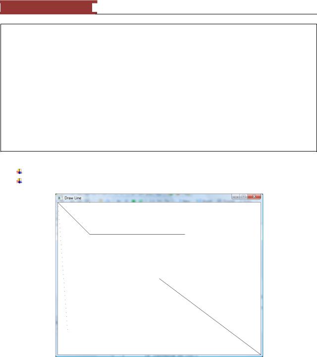
Figure 71 - Draw line algorithm #1
The program prints 5 lines but only one 3 of the lines display accurately – that is satisfying the criteria we have established for a good line drawing algorithm.. The vertical lines do not show since x0=x1 and dx = 0 which makes computing the slope impossible. The other line that appears more like a dotted line does not meet of the criteria of appearing continuous. This occurs when the slope > 1.
82
December 15, 2011 [LEARNING SDL – A BEGINNER’S GUIDE]
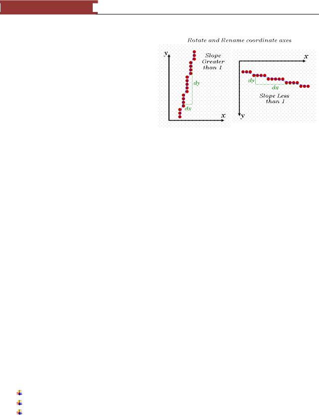
A Simple Algorithm #2 – Using Symmetry
We will use symmetry to solve the line drawing problem when m > 1. The assigning of one coordinate axis the name x and the other y is arbitrary. If m > 1 in one orientation (e.g. 3/2) than it is less than 1 if we switched orientations. (note for our screen drawings we actually used the second orientation!). We will modify the algorithm to switch the use of x and y when the slope > 1.
int dx = x1 – x0; |
|
int dy = y1y0; |
|
drawPixel(surface, x0, y0, color); |
// plot the first point |
if (abs(dx) > abs(dy) { |
// handles slope < 1 |
float m = (float) dy / (float) dx; |
// calculate the slope |
float b = y0 – m * x0; |
// compute the y-intercept |
dx = (x1 > x0) ? 1 : -1; |
|
while ( x0 != x1 ) { |
|
x0 += dx; |
// next x value |
y0 = round(m*x0 + b); |
// corresponding y value |
|
drawPixel(surface, x0, y0, color); |
|
} |
} else { |
// handles slope >= 1 |
|
float m = (float) dx / (float) dy; |
|
float b = x0 – m * y0; |
|
dy = (y1 > y0) ? 1 : -1; |
|
while (y0 != y1) { |
|
y0 +-=dy; |
|
x0 = = round(m*y0 + b); |
|
drawPixel(surface, x0, y0, color); |
|
} |
} |
|
LAB #6: Program 2_6 – Slope-Intercept Algorithm Improvement
Create a new project named Program2_6 using the template Simple SDL Project template. Enter the same program that was used in Program 2_5
Enhance your previous drawLine function to handle lines with slope >= 1.
83

December 15, 2011 [LEARNING SDL – A BEGINNER’S GUIDE]
You can see that all five lines are now drawn. The line going from (0,0) to (30,400) now looks more continuous but jagged! There are algorithms online (see Xiaolin Wu‘s Line Algorithm) that make the line appear ―straighter‖ by doing what is called anti-aliasing.
We really are not done since the algorithm could be greatly improved or what programmers call optimized by making some simple changes. Optimization will improve the speed in which the line is drawn. If you want to continue working on the example I invite you to check out the web for ideas and better algorithms.
Figure 72 - Draw line algorithm #2
See the exercises at the end of this Chapter for ideas on how to draw circles.
SDL_Rect
The next SDL structure to learn is SDL_Rect. This is an essential data structure since any graphics element you want to draw on the screen has to fit within a rectangular space – yes that goes for game paddle, image of monsters and even balls!
typedef struct SDL_Rect { Sint16 x, y;
Uint16 w, h; } SDL_Rect;
84

December 15, 2011 [LEARNING SDL – A BEGINNER’S GUIDE]
The structure contains four members, the upper-left position of the rectangle specified by x and y and the rectangle width (w) and height (h). Using the information in SDL_Rect you can compute the other edge points of the rectangle as illustrated:
(x,y) |
(x+w-1,y) |
(x,y+h-1) |
(x+w-1,y+h-1) |
Figure 73 - SDL_Rect
The key figure below illustrates the actual grid positions that would be affected by creating an SDL_Rect starting at (10,10) with w=5 and h=3 are
(10,10)(11,10)(12,10)(13,10)(14,10)
(10,11)(11,11)(12,11)(13,11)(14,11)
(10,12)(11,12)(12,12)(13,12)(14,12)
Note, how the pixels that are part of the rectangle go from (x,y). . . (x+w-1, y) NOT (x+w)
The way the math works the actual column x+w is not part of our rectangle nor is the row y+h. It is easy to determine if a Point P (x2, y2) is inside or outside the rectangle.
(x,y) |
(x+w-1,y) |
|
Point (x2,y2) ? |
(x,y+h-1) |
(x+w-1,y+h-1) |
Figure 74 - Determining if a point P(x2, y2) is inside or outside?
To determine if Point(x2, y2) is inside or outside the rectangle one need only use the following formula:
if ( x2 >= x && x2 < (x+w) && y2 >= y && y2 < (y+h) ) {
85

December 15, 2011 [LEARNING SDL – A BEGINNER’S GUIDE]
// inside the rectangle
} else {
// outside the rectangle
}
Why do you care about something so simple? Well, we would like to be able to determine when one rectangular object has collided with another so we have to first understand how to test a simple point. We will return to this topic later.
If the previous lab exercises I actually used the SDL_Rect structure to make the entire screen white by using the following lines:
// Make the background screen white
SDL_Rect screenRect = {0,0, SCREEN_WIDTH, SCREEN_HEIGHT};
Uint32 color = SDL_MapRGB(pDisplaySurface->format, COLOR_WHITE.r, COLOR_WHITE.g, COLOR_WHITE.b);
SDL_FillRect(pDisplaySurface, &screenRect, color);
The code creates an SDL_Rect variable – screenRect with the dimensions of the screen, then uses the SDL_MapRGB to obtain the actual screen color for white (using the constant we created COLOR_WHITE that already specified the r, g, and b values required to obtain the color white). Finally, the code used a new function SDL_FillRect that takes our display surface pointer, the address of our rectangular area (variable screenRect) and color to make in our case the entire screen white.
Function Name: SDL_FillRect
Format:
int SDL_FillRect(SDL_Surface *pDisplaySurface, SDL_Rect * rectArea, Uint32 color);
Description:
This function performs a ―fast fill‖ of the given rectangle with the color specified. If rectArea = NULL then the entire display area is used (note, the SDL_Surface structure hold the w and h of the surface). The function returns 0 on success or -1 on error.
From the description above we could have made our screen white using only the following 2 lines of code:
// Make the background screen white
Uint32 color = SDL_MapRGB(pDisplaySurface->format, COLOR_WHITE.r, COLOR_WHITE.g, COLOR_WHITE.b);
SDL_FillRect(pDisplaySurface, NULL, color);
86

December 15, 2011 [LEARNING SDL – A BEGINNER’S GUIDE]
Figure 75 - Generating Random Rectangles
LAB #7: Program 2_7 – Generating Random Rectangles
Create a new project named Program2_7 using the template Simple SDL Project template. Enter the same program that was used in Program 2_4
Remove the function drawPixel and its prototype
Add code (after generating a random screen position) to generate a random width and height After the code that generates a random color into an SDL_Color use SDL_MapRGB to create the actual screenColor.
Add code to create and SDL_Rect variable named randomRect using the x,y, w and h values that were randomly generated
Add code to call SDL_FillRect
You may want to use SDL_Delay to delay for 300 milliseconds so you can see each rectangle being drawn as shown in the figure above.
Compile and run the program. Your screen should look like the one above.
Clipping
Clipping is the process of dividing the surface into two areas – its visible and invisible parts. By default when we create the display surface using SDL_SetVideoMode we can write to the entire screen – that is, the entire screen is visible. The SDL_Surface has a component named clip_rect which defines the surface clipping rectangle. We can change the portion of the screen that gets updated by changing this clipping rectangle. For example, suppose we wanted to add a screen border to the previous program. We can use the new function SDL_SetClipRect to define the new rectangular area that will be ―visible‖ or changeable by our random rectangles programs.
87
December 15, 2011 [LEARNING SDL – A BEGINNER’S GUIDE]
Function Name: SDL_SetClipRect
Format:
void SDL_SetClipRect(SDL_Surface *pDisplaySurface, SDL_Rect * rectArea);
Description:
This function sets the clipping rectangle for a surface (it is not limited to our display surface). Only those pixels that fall into the clipping area specified by rectArea will be displayed. If rectArea is set to NULL the clipping area will be set to the full size of the surface.
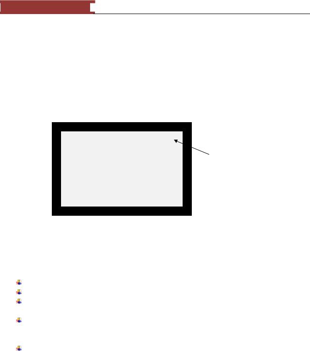
Clipping |
Rectangle |
Figure 76 - Example of creating a clipping rectangle
Anything you draw to the display screen will be restricted to the clipping rectangle, that is, anything outside of the clipping area will not be drawn.
LAB #8: Program 2_8 – Generating Random Rectangles with a Border
Create a new project named Program2_8 using the template Simple SDL Project template. Enter the same program that was used in Lab #7.
We will create a 20 pixel border on the top, bottom, left and right on the display by creating a clipping rectangle similar to the one shown in Figure 76.
Add code after creating the pDisplaySurface to set the clipping rectangle by creating an SDL_Rect that starts at (20,20) and has a width of SCREEN_WIDTH-40 and height of SCREEN_HEIGHT-40. Invoke SDL_SetClipRect.
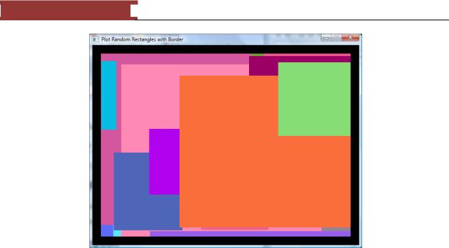
Compile and execute you should let the program run a while so that it fills out the screen. You should get screen display similar the one below.
88
December 15, 2011 [LEARNING SDL – A BEGINNER’S GUIDE]
Figure 77 - Setting a border using a clipping rectangle
SDL_VideoInfo
Information about the video display can be obtained by using the SDL function SDL_GetVideoInfo, the function returns an SDL_VideoInfo structure.
Function Name: SDL_GetVideoInfo
Format:
const SDL_VideoInfo* SDL_GetVideoInfo(void);
Description:
This function returns a READ-ONLY pointer to a structure containing information about the video hardware. If you call it before invoking SDL_SetVideoMode the structure member vfmt will contain the pixel format of the BEST video mode.
/** Useful for determining the video hardware capabilities */ typedef struct SDL_VideoInfo {
Uint32 hw_available :1; /**< Flag: Can you create hardware surfaces? */
Uint32 wm_available |
:1; /**< Flag: Can you talk to a |
window |
manager? */ |
Uint32 UnusedBits1 |
:6; |
|
|
Uint32 UnusedBits2 |
:1; |
|
|
Uint32 blit_hw |
:1; /**< Flag: Accelerated blits |
HW --> |
HW */ |
Uint32 blit_hw_CC |
:1; /**< Flag: Accelerated blits |
with Colorkey */ |
|
Uint32 blit_hw_A |
:1; /**< Flag: Accelerated blits |
with Alpha */ |
|
Uint32 blit_sw |
:1; /**< Flag: Accelerated blits |
SW --> |
HW */ |
Uint32 blit_sw_CC |
:1; /**< Flag: Accelerated blits |
with Colorkey */ |
|
89
December 15, 2011 [LEARNING SDL – A BEGINNER’S GUIDE]
Uint32 blit_sw_A |
:1; |
/**< Flag: Accelerated blits with Alpha */ |
|
Uint32 |
blit_fill |
:1; |
/**< Flag: Accelerated color fill */ |
Uint32 |
UnusedBits3 |
:16; |
|
Uint32 video_mem; /**< |
The total amount |
of video memory (in |
K) */ |
||||||
SDL_PixelFormat *vfmt; |
/**< Value: The |
format of the video |
surface */ |
||||||
int |
current_w; |
/**< |
Value: The |
current |
video |
mode |
width */ |
||
int |
current_h; |
/**< |
Value: The |
current |
video |
mode |
height |
*/ |
|
} SDL_VideoInfo;
LAB #9: Program 2_9 – Displaying video information before and after calling SDL_SetVideoMode.
Create a new project named Program2_9 using the template Simple SDL Project template. Add the following two functions and the required prototypes:
void writeVideoInfo(void) {
const SDL_VideoInfo *vInfo = SDL_GetVideoInfo(); if (vInfo->hw_available)
cout << "hw available, can create hardware surfaces" << endl;
else
cout << "hw NOT available, cannot create hardware surfaces" << endl;
if (vInfo->wm_available)
cout << "wm available, can talk to window manager" << endl;
else
cout << "wm NOT available, cannot talk to window manager" << endl;
if (vInfo->blit_hw)
cout << "blit_bw, supports accelerated blits HW-->HW" << endl;
else
cout << "blit_bw, DOES NOT support accelerated blits HW-->HW" << endl;
if (vInfo->blit_hw_CC)
cout << "blit_bw_CC, supports accelerated blits with Colorkey" << endl;
else
cout << "blit_bw_CC, DOES NOT support accelerated blits with Colorkey" << endl;
if (vInfo->blit_hw_A)
cout << "blit_bw_A, supports accelerated blits with Alpha" << endl;
else
cout << "blit_bw_A, DOES NOT supports accelerated blits with Alpha" << endl;
if (vInfo->blit_sw)
cout << "blit_sw, supports accelerated blits SW-->SW" << endl;
else
cout << "blit_sw, DOES NOT support accelerated blits with SW--
>SW" << endl;
90