

Speedier semiconductor chips
The ongoing microelectronics revolution was ushered in some 30 years ago by the introduction of silicon-based' semiconductor chips- The circuit speeds in some advanced computer equipment are now approaching the theoretical limits of silicon, and for many years scientists have been experimenting with faster-working alternative materials.2 Harris Microwave Semiconductor, of Milpitas, Calif., recently introduced two digital integrated circuits3 (IC) made from one exotic alternative to silicon: gallium arsenide. Electronic chips made from gallium arsenide have been available in the past, but usually only on a prototype basis. The new Harris chips, both of which are designed for use in sophisticated telecommunications equipment and military electronic systems, are the first commercially available off-the-shelf4 gallium-,arsenide IC chips. The manufacturer says they work five times faster than the speediest of today's silicon-based counterparts.
III. The computer principles, structure and operation binary system
Digital logic circuits require Just two levels of signal, high or low voltage. Using binary notation, a high voltage can be used to represent а йгпагу digi^ (bit) whose value is 1, and a low voltage to represent a 0.
Different combinations of Is and Os may be used to represent numbers and characters (letters of the alphabet and special characters). It is possible to carry out arithmetic operations on binary numbers in a similar way5 to that used for decimal numbers. Digital logic circuits can be built which store numbers in binary form, and others which can perform arithmetic operations on the stored numbers.
Many computers use groups of eight binary digits for encoding characters. A group of eight bits is called a byte. For simplicity, we will start by considering groups of four bits only for binary arithmetic operations.
We know the value that a decimal number represents by
1 silicon-based -- h;i оакпн' кремния
1; alternative materials — материалы-заменители
' digital integrated circuit цифрчния интегральная, c'a'ivia
'' off-the-shelf имеющийся ” наличии, и продаже
г' in a similar way - аналогичным образом
virtue of the positions of the decimal digits.' The position of each digit schows which power of 10 it should be multiplied by.2 For example, the number 8527 is equal to:
8xwз+5x\o2-^-2xlo} ^7x\o°
Remember that any number raised to the power O3 is equal to 1.
Binary numbers are represented in a similar way, but the binary digits (0 or I) are multiplied by the appropriate power of 2. For example, decimal !3 (13ю) is represented by the following binary pattern:4
1101
since I XS3^- I X22^0X2^+ 1 х2°=13ц,.
That is, 13io=110l2.
The maximum decimal number that can be represented by four bits is 15ю fl Ilia). For larger numbers extra bit positions need to be used.5 For example,
1010l2=lx24+l X22+1 X 2°+21 ю-
Logic circuits
Boolean Operators
Logical decisions may be defined using bits 1 and 0 to represent the on and off states, or high and low voltages, in logic circuits.
Boolean algebra is a two-state, symbolic algebra which combines two bits (the input" signals) by means of Boolean operators to produce a 1-bit output signal. Boolean algebra is used extensively in the analysis of logic circuits to determine the output from circuits which perform the functions of the Boolean operators.
The output signals from all possible combinations of the input signals are shown in Truth Tables.6 The name is derived from the original use of Boolean algebra for determining the truth or falsity of propositions.7
' We know the value that a decimal number represents by virtue of the positions of the decimal digits. - Нам известна величина, котирую приставляет гобой десятичное число, благодаря позиции, занимаемой каждым его десяти ч id,] м разрядом.
2 shows which power of 10 it should be multiplied by показывает, на какую степень числа 10 его следует умножить
3 raised to the power 0 — возведение в нулевую степень
4 by the following binary pattern — по следующей бинарноя схеме
5 extra bit positions need to be used—необходимы дополнительные битовые
пози нии
h Truth Tables—Таблицы истинности ' for determining the truth or falsity of propositions — дли установления
Ш.Ч11ИЧИСТИ или ложности суждения
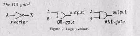
The OR operator'
The Boolean algebra symbol for OR is +. We will represent the two input signals by A and B.
The Truth Table for the OR operation is given in Table 1. This shows that the output signal is 1 only if A or B, or both are equal to 1.
Table {. Truth Table for OR operation
Inputs |
Output |
|
A |
В |
|
0 0 |
о ] |
0 1 |
1 1 |
[ 1 |
! 1 |
The AND operator2
The AND operator is represented by a multiplication sign ( • }. The Truth Table for this operation is given in Table 2. This shows that the output signal is 1 only if A and B are both 1.
Table 2. Truth Table for AND operation
Inputs |
Output |
|
A |
В |
|
(1 |
о |
0 |
0 |
1 |
0 |
1 |
о |
о |
1 |
i |
1 |
The .exciusive-OR operator3
The exciusive-OR (XOR) operator is represented by the symbol @ . The Truth Table for this operation is given in Table 3. Notice that XOR allows us to detect if the two input signals are different (output 1) or the same {output 0).
' the OR operator — оператор “ИЛИ”
2 the AND operator — оператор “И”
3 the exciusive-OR operator - оператор “исключающее ИЛИ”
Table 3. Truth Table tor XOR operation
Inputs |
Output |
|
A |
В |
|
0 |
о |
0 |
0 |
1 |
1 |
1 |
о |
1 |
1 |
1 |
0 |
The NOT operator'
The NOT operator is different from the other three operators described, since it is not used to combine input signals but to invert a single input signal, i. e. the output signal from NOT A is 0 if A is 1 and 1 if A is 0. The operator is represented by a bar over the input symbol. For example, if A is 1
A = T = 0. Logic Gates
A logic gate consists of a circuit with one or more input signals of high or low voltage, which produces one output signal. The latter will be a high or low voltage depending on the type of gate and the nature of the input signals,
Each type of gate may be represented by a standard symbol on a logic diagram. The following sections give examples of the different gates that may be used in logic circuits,
The Inverter (NOT gale}2
The logic symbol for an inverter is shown in Figure 1. Remember that a NOT gate Just inverts the input signal. We shall see later how this gate may be used in circuits where the complement of "the input sip-nal is required.
' the NOT operator - опгратор “HP”
; NOT gate схема “НЕ”
:1 OR gate - o.t'\)a “ИЛИ”
Microelectronic Implementation of Logic Circuits
Each type of logic circuit may be implemented as a microelectronic circuit using microelectronic transistors and resistors.
The actual implementation depends on the type of semiconductor technology used, and on requirements related to the use of the microelectronic circuits.
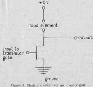
For example, an inverter may be constructed using an n-MOS transistor and a load element in series.' The load element limits the current flowing through the transistor when the supply voltage is applied, as shown in Figure 3- The input signal is applied to the gate of the transistor; the latter will only conduct when the signal to the transistor gate is high. In this case, there wilt be a voltage drop across the load element so that the output is low.
Conversely, when the signal applied to the transistor gate is low; there is no conduction path to ground and hence no voltage drop across the load element, giving high output.2 The load element for this type of gate can be a resistor or another transistor. Different types of load elements result in changes in the characteristics of the circuits with respect to such factors as3 ease of fabrication, packing density and power consumption.
' in series bk,iiki'k'|iiii.k' iii)i.'ju';i.""|i кмыю 2 hence no voltage drop across the load element, giving high output—niminn
н.шряжгшк' на narpy:tKC w ii;i;'l;if'T. чти cat.'i.it.'i DbKiihw m.i'“141100 наиряжсми. •' wilh respect to such factors as в отношении таких факторов. как
li”
A wide variety of integrated circuits are commercially available for different applications. Some of these comprise just a few logic gates, others have complex circuitry containing- m;my thousands of gates.