- •Учреждение образования «высший государственный колледж связи» «чтение и перевод технических текстов по специальности ткс»
- •Часть I
- •Введение
- •Unit 1 (17) Antennas
- •17.1 Types of antennas
- •17.1.1 Antennas used in communications
- •17.2 Basic properties
- •17.3 Generic antenna types
- •17.3.1 Radiation from apertures
- •1 Learn the words & word combinations:
- •2 Read & translate the text (orally) 17.1 – 17.3.2:
- •5 Answer the questions:
- •17.3.2 Radiation from small antennas
- •17.3.3 Radiation from arrays
- •17.4 Specific antenna types
- •17.4.1 Prime focus symmetric reflector antennas
- •17.4.1.1 Parabolic reflectors
- •17.4.1.2 Aperture fields and radiation patterns
- •17.4.1.3 Gain of reflector antennas
- •1Learn the words & word combinations:
- •2 Read & translate the text (orally) 17.3.2 – 17.4.1:
- •5 Answer the questions:
- •17.4.2 Dual symmetric reflector antennas
- •17.4.3 Offset reflectors
- •17.4.4 Horn feeds for reflector antennas
- •17.4.4.1 Rectangular or square horns
- •17.4.4.2 Small conical horns
- •17.4.4.3 Multi-mode conical horns
- •17.4.4.4 Conical corrugated horns
- •17.4.4.5 Array feeds
- •1 Learn the words & word combinations:
- •2 Read & translate the text (orally) 17.4.2 – 17.4.4:
- •5 Answer the questions:
- •17.5 Antennas used in communication systems
- •17.5.1 Microwave line of sight radio
- •17.5.2 Earth station antennas
- •1 Learn the words & word combinations:
- •2 Read & translate the text (orally) 17.5.1 – 17.5.2:
- •5Answer the questions:
- •17.5.3 Satellite antennas
- •17.5.3.1 Telemetry, tracking and command (tt&c)
- •17.5.3.2 Spot beams
- •17.5.3.3 Multiple beams
- •17.5.3.4 Shaped beams
- •17.5.4 Vhf and uhf communications
- •17.5.5 Hf communications
- •1 Write out the words and word combinations which are still unknown to you and learn them. Unit 2 (20) Frequency division multiplexing
- •20.1 Fdm principles
- •20.2 History
- •20.3 Fdm hierarchy
- •20.3.1 General considerations
- •20.3.2 Channel bandwidth
- •20.3.3 Group and supergroup
- •20.3.4 Higher order translation
- •20.3.4.1 15 Supergroup assemblies
- •20.3.4.2 Mastergroup
- •20.3.4.3 Bell system
- •1 Learn the words & word combinations:
- •2 Read & translate the text (orally) 20.1 – 20.3.4:
- •4Find English equivalents:
- •5 Answer the questions:
- •20.4 Frequency translation
- •20.4.1 Ring bridge modulator/demodulator design considerations
- •20.4.1.1 Carrier compression.
- •20.4.1.2 Carrier and signal suppression
- •20.5 Carriers
- •20.5.1 Carrier frequency accuracy
- •20.5.2 Carrier purity
- •20.5.3 Carrier level
- •20.6 Pilots
- •20.6.1 Translation equipment pilots
- •20.6.1.1 Use of reference pilots for automatic gain control
- •20.6.2 Line equipment pilots
- •20.6.2.1 Regulation pilots
- •20.6.2.2 Frequency comparison pilots
- •1 Learn the words & word combinations:
- •2 Read & translate the text (orally) 20.4 – 20.6
- •5. Answer the questions:
- •20.7 Noise contributions
- •20.7.1 Definitions
- •20.7.2 Psophometric weighting
- •20.7.3 Thermal noise
- •20.7.4 Noise due to unlinearity
- •20.7.4.1 Single channel load
- •20.7.4.2 Multichannel load
- •20.7.4.3 Unlinearily characterisation
- •20.7.4.4 Determination ofunlinearity noise from a multichannel load
- •20.7.4.5 Approximate value for the weighted intermodulation noise contribution
- •20.7.4.6 Weighted noise power in pWOp
- •20.7.4.7 Determination of unlinearity noise using spectral densities
- •1 Learn the words & word combinations:
- •2 Read & translation the text (orally) 20.7:
- •5 Answer the questions:
- •20.8 Measurement of noise contributions
- •20.9 Overload
- •20.9.1 Overload measurement.
- •20.9.1.1 Harmonic/intermodulation products
- •20.9.1.2 Gain change
- •20.10 Hypothetical reference system
- •20.10.1 Noise contributions
- •20.10.2 Line sections
- •1 Learn the words & word combinations:
- •2 Read & translate the text (orally) 20.8 -20.10:
- •5 Answer the questions:
- •20.11 Companding
- •20.11.1 Compander characteristics
- •20.11.2 Multichannel load increase
- •20.11.3 Compandor noise advantage
- •20.13 Transmultiplexers
- •20.13.1 Synchronisation
- •20.13.2 Pcm alarms
- •20.14 Repeatered cable line equipment
- •20.14.1 Pre-Emphasis
- •20.14.2 Thermal noise
- •20.14.3 Regulation
- •20.14.3.1 Regulation range
- •20.14.4 Power feeding
- •Translate the text 20.11 – 20.14.4
- •Translate in written form point 20.13 “Transmultiplexers”
- •«Чтение и перевод технических текстов по специальности ткс»
- •Часть I
17.4.1.2 Aperture fields and radiation patterns
Ray optics indicates that the path length from F to P to A is equal to twice the focal length. Hence the phase across the aperture is constant. The amplitude across the aperture plane will peak at the centre and taper towards the edge for two reasons. Firstly because the feed will have a tapered adiation pattern and secondly because the action of a parabola in transforming a spherical wave from the feed into a plane wave across the aperture introduces a path loss which is a function of angle 6. The aperture electric field is then given by Equation 17.17, where F( 9,<p ) is the pattern of the feed.
Feeds suitable for reflector antennas are discussed in a later section, but it is often convenient in initial design to take the feed pattern as being given by Equation 17.18.
Experience has shown that good quality feeds approximate well to this function.
The radiation patterns can be predicted from the aperture fields by using the Fourier transform relations described in Section 17.3.1. This works well for large retlectors but for detailed design of small to medium retlectors it is necessary to take account of the precise form of the currents on the reflector surface and the diffraction that occurs at the edges of the reflector surface. The former can be accomplished with Physical Optics theory (Rusch, 1970; Rusch, 1986) and is good for predicting the main beam and near-in sidelobes. The diffracted fields influence the far-out sidelobes and can be predicted using the Geometrical Theory of Diffraction (GTD) (James, 1986).
17.4.1.3 Gain of reflector antennas
The gain of a reflector antenna can be calculated from Equation 17.19, where r\ is the efficiency of the reflector.
The total efficiency is the product of six factors:
The illumination efficiency is the gain loss due to the non-uniform aperture illumination.
The spillover efficiency is the gain loss caused by energy from the feed which radiates outside the solid angle subtended by Bo called the spillover. It is the fraction of the power which is intercepted by the reflector. As the aperture edge taper in creases, the spillover decreases and the spillover efficiency increases, whilst the illumination efficiency decreases. There is an optimum combination which corresponds to an edge illumination of about -10 dB.
The phase error efficiency is a measure of the deviation of the feed face front away from spherical and is usually nearly 100%.
The crosspolarisation efficiency is a measure of the loss of energy in the orthogonal component of the polarisation vector. For a symmetric reflector no crosspolarisation is introduced by the reflector so the efficiency is determined by the feed characteristics. For good feeds this factor is also nearly 100%.
The blockage efficiency is a measure of the portion of the aperture which is blocked by the feed and the feed supports. The fields blocked by the feed do not contribute to the radiation so it is desirable to keep the proportion of the area blocked to less than 10% of the total area of the aperture because otherwise the sidelobe structure becomes distorted. The feed support blocking is more complicated because it depends on the shape and orientation of the supports (Lamb, 1986). It is electrically desirable to keep the cross-section of the supports mall which means that a compromise with the mechanical constraints is needed.
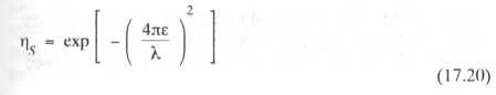
The surface error efficiency is a measure of the deviations of the aperture wavefront from a plane wave due to surface distortions on the parabolic surface. Assuming that the errors are small and randomly distributed with a root mean square (r.m.s.) surface error, the efficiency is given by Equation 17.20. This is a function of frequency and falls-off rapidly above a certain value which means that the upper frequency for which a reflector can be used is always given by the surface errors. The effect on the radiation pattern of random surface errors is to fill in the nulls and to scatter energy in all directions so that the far out sidelobes are uniformly raised.