

20.4.1.2 Carrier and signal suppression
This is also known as carrier 'leak' and signal 'leak'. Perfect balance of modulator referred to above is not possible in practice. The best balance that can be achieved in a manufacturing environment is in the order of 30dB.
There will therefore be some unwanted products at the output of the modulator that will have to be removed by filtering before presentation to the combined path. Filter Fa (see Figure 20.1) requirements are shown i n Table 20.1. The requirement is higher for the signal leak and the upper sideband as these products will give rise to crosstalk.
20.5 Carriers
20.5.1 Carrier frequency accuracy
For
some services, particularly data circuits, it is desirable that the
'virtual'
carrier difference over a network is maintained to within 2Hz.
(CCITT, 1985.) To achieve this the carrier generation master
oscillators
receive regular maintenance adjustment using a reference
frequency comparison pilot (see Section 20.6.2.2) or in later
developed systems are phased locked to the frequency comparison
p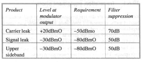 ilot.
ilot.
The recommended stability of the carrier frequencies are given in Table 20.2. With this carrier accuracy the end to end difference in virtual carriers will exceed 3Hz for 1 % of the time and 4Hz for 0.1% of the time over a hypothetical international link of 2500km.
20.5.2 Carrier purity
This is as follows:
Harmonics less than -20dBmO.
Purity against other carriers and side products related to 4kHz less than -80dBmO.
Spurious sidebands are produced by the carrier impurities during the modulation process and these create both intelligible and unintelligible crosstalk. The level of the 'ghost' sidebands is related to the level of the impurity of the carrier. (Tucker, 1948.)
20.5.3 Carrier level
Carriers are generated at a high level (+25dBm) for distribution to the translating equipment. Each equipment normally requires two supplies at a power level of approximately +10 to +13dBm in order to drive the modulator and demodulator.
20.6 Pilots
20.6.1 Translation equipment pilots
Reference pilots are discrete frequencies added to each translated band of traffic channels for monitoring and automatic gain control regulation at the far end of the transmission path. Some of the more common reference pilots are given in Table 20.3.
Additional pilots can be added for measurement or monitoring of wide band systems and are usually positioned in the gaps between supergroups. These are called intersupergroup pilots.
20.6.1.1 Use of reference pilots for automatic gain control
The normal practice is to provide gain or loss correction to the traffic path at the received end of transmission using the pilot to control the correction. (See Figure 20.8). This correction is applied most commonly at group and supergroup level.
Correction is applied to maintain the design traffic level across the circuit link which may contain many stages of translation and several tandem connected line systems. Seasonal temperature changes to the cable link is foremost in the contributing factors. The correction is applied equally across the frequency band and with an Automatic Gain Control ratio of approximately 10:1.
Thermistors are normally used as gain control elements to avoid any unlinearity distortion to the traffic path. In addition the slow thermal time constant is suited to the slow diurnal gain change of the cable system and the envelope gain of the AGC relatively easy to control. ± 4dB regulation range is normally required from AGC equipments.