

Mechanical_Intro_14.5_L06_Connections
.pdfLecture 6
Modeling Connections
14.5 Release
Introduction to ANSYS Mechanical

 Chapter Overview
In this chapter extend the discussion of contact control begun in the part 1 introductory course. We also introduce the mesh connection capability for use with surface models:
A.
B.
C.
D.
E.
F.
G.
H.
I.
J.
K.
L.
Contact
Contact Controls
Contact Results
Spot Welds
Mesh Connections
Connections Worksheet
Workshop 6.1 - Contact Offset Control
Joint Definitions
Joint Configuration
Joint Stops and Locks
Springs and Beams
Workshop 6.2 - Using Joints
2 |
© 2012 ANSYS, Inc. |
December 19, 2012 |
Release 14.5 |
 A. Contact
In this course we will touch on some of the concepts relating to contact analysis. Keep in mind, however, contact is a highly nonlinear feature and is covered in its entirety in the Mechanical Nonlinearitiestraining course.
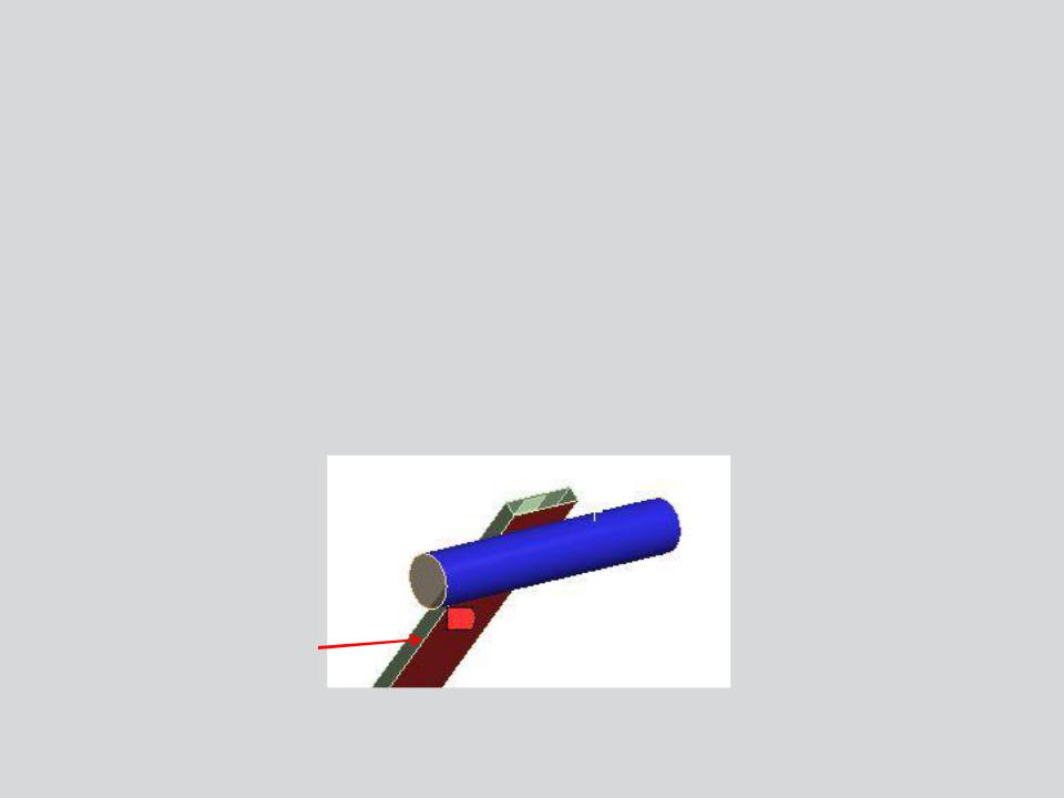
•Contact elements can be thought of as a “skin” covering the surfaces that are expected to interact with one another.
•One side of a contact pair is referred to as the “contact” and its mate as the “target”.
•Mechanical uses a color coding system to differentiate the contact and target surfaces.
 Target
Contact
3 |
© 2012 ANSYS, Inc. |
December 19, 2012 |
Release 14.5 |
 … Contact
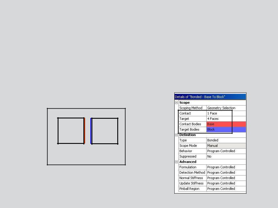
•One side of a contact pair is referred to as a contact surface, the other side is referred to as a target surface.
–Contact and target scoping does not need to be equal. For example, a contact can be scoped to 2 faces while its target is scoped to 5 faces.
•Contact pairs are color coded in the details and on the geometry.
2D Contact Pair
4 |
© 2012 ANSYS, Inc. |
December 19, 2012 |
Release 14.5 |

 . . . Contact
Contact regions are automatically created between parts during assembly import.
•Contacts are contained in the Connections branch and can be grouped in multiple
“Contacts” folders.
–Contact detection tolerance controls are available (low = loose tolerance; high = tight tolerance).
Loose |
Tight |
5 |
© 2012 ANSYS, Inc. |
December 19, 2012 |
Release 14.5 |

 … Contact
Five contact behaviors are available:
|
|
|
|
|
|
|
|
|
|
|
Contact Type |
|
Iterations |
|
Normal Behavior (Separation) |
|
Tangential Behavior (Sliding) |
|
|
|
Bonded |
|
1 |
|
No Gaps |
|
No Sliding |
|
|
|
No Separation |
|
1 |
|
No Gaps |
|
Sliding Allowed |
|
|
|
|
|
|
|
|
|
|
|
|
|
Frictionless |
|
Multiple |
|
Gaps Allowed |
|
Sliding Allowed |
|
|
|
Rough |
|
Multiple |
|
Gaps Allowed |
|
No Sliding |
|
|
|
Frictional |
|
Multiple |
|
Gaps Allowed |
|
Sliding Allowed |
|
|
|
|
|
|
|
|
|
|
|
|
•Bonded and No Separation contact are linear and require only 1 iteration.
–Bonded: surfaces are fixed to one another so no gaps can open and no sliding takes place.
–No Separation: no gaps can open however small sliding can take place.
•Frictionless, Rough and Frictional contact are nonlinear and require multiple iterations. These contact types will be introduced here but detailed fully in the ANSYS Mechanical Structural Nonlinearities training course.
6 |
© 2012 ANSYS, Inc. |
December 19, 2012 |
Release 14.5 |
 … Contact
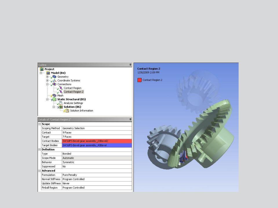
When a contact region is highlighted in the connections branch, parts are made translucent for easier viewing.
• Contact surfaces are color coded for easy identification.
7 |
© 2012 ANSYS, Inc. |
December 19, 2012 |
Release 14.5 |
 … Contact
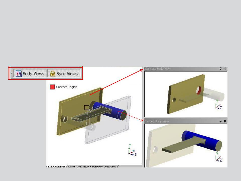
For ease of viewing or selecting, “Body Views” can be activated:
•Separate windows display the full model, contact body and target body.
•Views can be “synched” (all windows move together).
•Selecting (for contact scoping) can be done in any window.
8 |
© 2012 ANSYS, Inc. |
December 19, 2012 |
Release 14.5 |
 … Contact
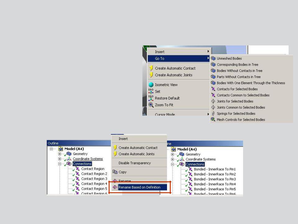
“Go To” utilities provide a simple way of verifying contact definitions:
•Bodies without contact
•Parts without contact
•Contact regions for selected bodies
•Contacts common to selected bodies
•Correspondingbodies in tree
•Contacts can be quickly renamed to match part names
RMB
9 |
© 2012 ANSYS, Inc. |
December 19, 2012 |
Release 14.5 |
 … Contact
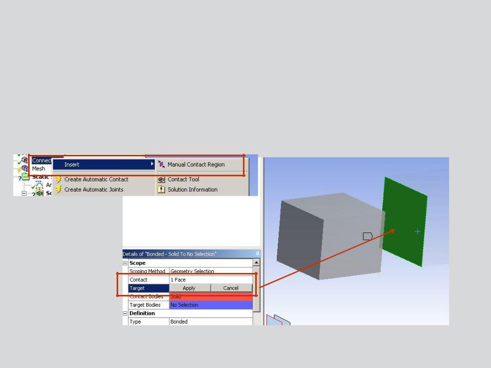
Where surfaces are not automatically detected a manual contact pair can be defined.
•Insert a manual contact region and select the “contact” and “target” surfaces.
RMB
10 |
© 2012 ANSYS, Inc. |
December 19, 2012 |
Release 14.5 |