

Mechanical_Intro_14.5_L06_Connections
.pdf B. Contact Controls
In Mechanical one side of a contact pair is referred to as the contact while the other is referred to as the target.
•By default (Program Chosen) Mechanical uses what is called auto-asymmetric contact.
•In some situations there is a “preferred” for which side is designated the contact versus the target. Since the solver does not determine this preference ahead of time, initially a contact pair is duplicated (symmetric contact). When the solver detects the preferred arrangement one of the contact pairs is removed. This is called asymmetric contact.
|
|
|
|
|
|
|
|
|
|
|
|
|
|
|
|
|
|
|
|
|
|
|
|
|
|
|
Symmetric |
|
|
Asymmetric |
|
|||||||
|
Contact |
|
|
|
||||||||
|
|
|
Contact |
|
||||||||
|
|
|
|
|
|
|
|
|
|
|||
|
|
|
|
|
|
|
|
|
|
|
|
|
11 |
© 2012 ANSYS, Inc. |
December 19, 2012 |
Release 14.5 |

 . . . Contact Controls
Nonlinear contact types allow an “interface treatment” option:
–“Add Offset”: input zero or non-zero value for initial adjustment.
–“Adjusted to Touch”: ANSYS closes any gap to a just touching position
|
|
|
|
C |
|
|
C |
|
T |
|
|
T |
|
|
|
|
|
|
|
|
Add offset: positive or negative |
|
can be ramped on. |
Adjusted to touch |
12 |
© 2012 ANSYS, Inc. |
December 19, 2012 |
Release 14.5 |

 . . . Contact Controls
Interface treatment example modeling a press fit:
The geometry model contains a pin in a hole which are of the same diameter. Contact offset is used to simulate a press fit of an over sized pin. The resulting stress plot is shown.
13 |
© 2012 ANSYS, Inc. |
December 19, 2012 |
Release 14.5 |

 . . . Contact Controls
The Pinball Region is a zone that designates far field or near field open contact status (inside or outside the radius). It can be thought of as a zone bordering each contact region.
The pinball’s main purpose is to provide efficiency when solving contacts which are “far” apart. For most applications simply use the program controlled setting.
During this course we’ll point out several situations where it may be useful to manually control the pinball radius. 
Pinball radius
14 |
© 2012 ANSYS, Inc. |
December 19, 2012 |
Release 14.5 |
 . . . Contact Controls
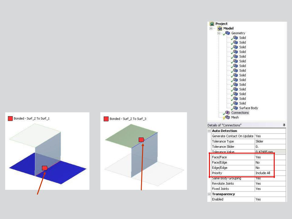
Shell contact includes face-to-face, edge-to-face or edge-to edge contact:
•Automatic shell contact is not turned on by default but can be set to detect face-to-edge or edge-to-edge contact.
•Priority can be set to prevent multiple contact regions in a given region.
Edge to Edge
Edge to Surface
15 |
© 2012 ANSYS, Inc. |
December 19, 2012 |
Release 14.5 |

 . . . Contact Controls
Several unique aspects of surface geometry must be addressed when using contact:
|
|
With a single face it’s important to |
|
|
|
identify which side is to be used. |
|
|
|
The “top” of a surface is the one |
|
Top |
|||
|
that highlights when selected. |
||
|
|
||
|
|
|
|
|
|
|
|
|
|
|
|
|
|
|
|
|
|
|
|
|
|
|
|
|
|
|
|
|
|
|
Representingsurface geometry |
|
|
|
|
|
|
|
often means gaps will exist where |
|
|
|
|
|
|
|
|
|
||
|
Bottom |
|
|
the “real” surface would be. |
|
|
|
|
|
|
|
|
|
|
|
|
|
|
|
|
|
|
|
|
|
|
|
|
|
|
|
16 |
© 2012 ANSYS, Inc. |
December 19, 2012 |
Release 14.5 |

 . . . Contact Controls
The details for surface contact contain controls for assigning contact to the top or bottom of a shell as well as including the effect of the thickness of the shell. Including the thickness effect here means the gap will be ignored and the surfaces will behave as if they were in contact.
In this example by activating the shell thickness effect we are assuming the initial configuration is as shown here. Just touching
|
|
|
|
|
|
Release 14.5 |
17 |
© 2012 ANSYS, Inc. |
December 19, 2012 |
|
|
||
|
|
|||||
 C. Contact Results
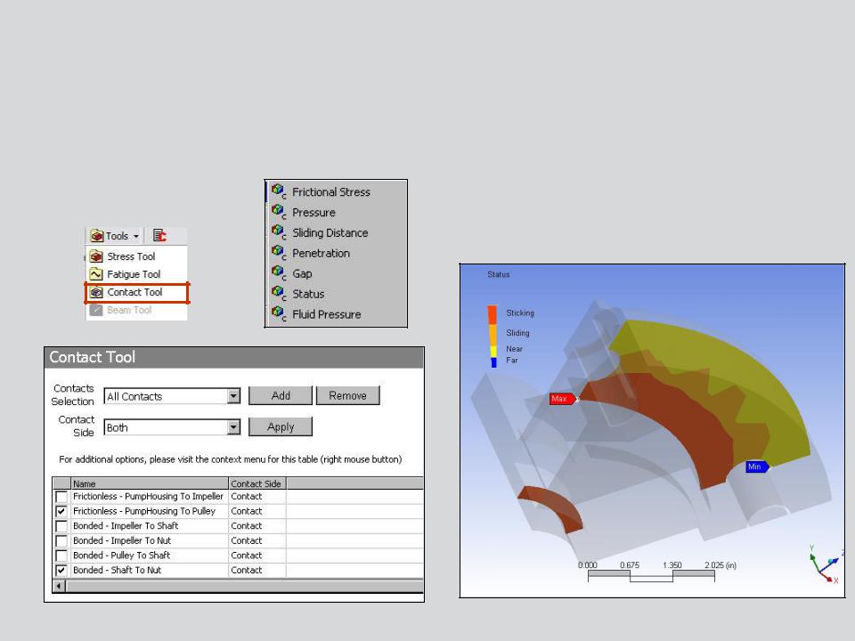
Contact specific results are requested via a “Contact Tool”.
•Geometry selection or a worksheet (shown below) can be used to choose the contacts of interest.
18 |
© 2012 ANSYS, Inc. |
December 19, 2012 |
Release 14.5 |

 . . . Contact Results
Contact results are displayed on the contact side only. With auto-asymmetric contact, since the solver chooses which side is designated contact it may not be obvious at the outset which side will display the results.
In this example the original contact/target designation was flipped by the solver.
A zero result will be displayed on the target side of a contact pair as shown in the top figure.
19 |
© 2012 ANSYS, Inc. |
December 19, 2012 |
Release 14.5 |

 D. Spot Welds
Spot welds provide a means of connecting shell assemblies at discrete points:
•Spotwelds are defined on the geometry as vertex point pairs. Currently, only DesignModeler and NX can be used to create automatic spot welds (note, spot welds can be defined manually if vertices exist in the proper locations).
•The spot weld connection is accomplished using a beam connection between the points.
•A “spider web” of beams is radiated from each point to distribute the load.
20 |
© 2012 ANSYS, Inc. |
December 19, 2012 |
Release 14.5 |