

Mechanical_Intro_14.5_L05_Static
.pdfLecture 5
Static Structural Analysis
14.5 Release
Introduction to ANSYS Mechanical

 Chapter Overview
In this chapter, performing linear static structural analyses in Mechanical will be covered:
A.Basics of Linear Static Analysis
B.Geometry
C.Material Properties
D.Contact
E.Analysis Settings
F.Loads
G.Supports
H.Nodal Loads and Supports
I.Load and Support Display
J.Solving Models
K.Workshop 5.1, Pump AssemblyWith Contact
L.Results and Postprocessing
M.Workshop 5.2, Using Beam Connections
2 |
© 2012 ANSYS, Inc. |
December 19, 2012 |
Release 14.5 |

 A. Basics of Linear Static Analysis
The schematic setup for a linear static structural analysis is shown here.
3 |
© 2012 ANSYS, Inc. |
December 19, 2012 |
Release 14.5 |

 . . . Basics of Linear Static Analysis
For a linear static structural analysis, the displacements {x} are solved for in the matrix equation below:
K x F
Assumptions:
•[K] is constant
–Linear elastic material behavior is assumed
–Small deflection theory is used
•{F} is statically applied
–No time-varying forces are considered
–No damping effects
It is important to remember these assumptions related to linear static analysis. Nonlinear static and dynamic analyses are covered in other training courses.
4 |
© 2012 ANSYS, Inc. |
December 19, 2012 |
Release 14.5 |

 B. Geometry
In structural analyses, all types of bodies supported by Mechanical may be used.
For surface bodies, thickness must be supplied in the “Details” view of the “Geometry” branch.
The cross-section and orientation of line bodies are defined within DesignModeler and are imported into Mechanical automatically.
5 |
© 2012 ANSYS, Inc. |
December 19, 2012 |
Release 14.5 |

 . . . Geometry
•Mechanical allows a part’s stiffness behavior to be defined as “rigid” or “flexible”.
–A rigid body is not meshed with traditional finite elements. Rather it is represented using a single mass element and is thus very efficient in terms of solution times.
–Parts in an assembly that are included only to transfer loads can be designated as rigid to reduce solution times and model sizes.
6 |
© 2012 ANSYS, Inc. |
December 19, 2012 |
Release 14.5 |

 … Point Mass
A Point Mass can be added to a model’s Geometry branch to simulate parts of the structure not explicitly modeled:
• A point mass can be scoped to surfaces,edges or vertices.
•The location can be defined by either:
–(x, y, z) coordinates (global or local).
–Selecting vertices/edges/surfaces to define location.
•Point mass is affected by “Acceleration,” “Standard Earth Gravity,” and “Rotational Velocity”. No other loads effect a point mass.
7 |
© 2012 ANSYS, Inc. |
December 19, 2012 |
Release 14.5 |
 C. Material Properties
Young’s Modulus and Poisson’s Ratio are required for linear static structural analyses:
•Density is required if any inertial loads are present.
•Thermal expansion coefficient is required if a temperature load is applied.
•Thermal conductivity is NOT required for uniform temperature conditions.
•Stress Limits are needed if a Stress Tool result is present.
•Fatigue Properties are needed if Fatigue Tool result is present.
– Requires Fatigue Module add-on license.
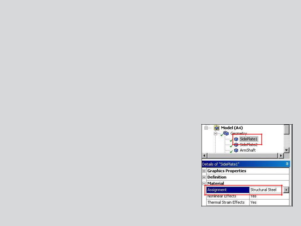
•As shown earlier material properties are assigned in the part details in Mechanical.
8 |
© 2012 ANSYS, Inc. |
December 19, 2012 |
Release 14.5 |
 D. Contact
Surface contact elements in Mechanical can be visualized as a “skin” covering the surfaces of the parts in an assembly.
It is these elements that define the behavior when parts are in contact (e.g. friction, bonding, heat transfer, etc.).
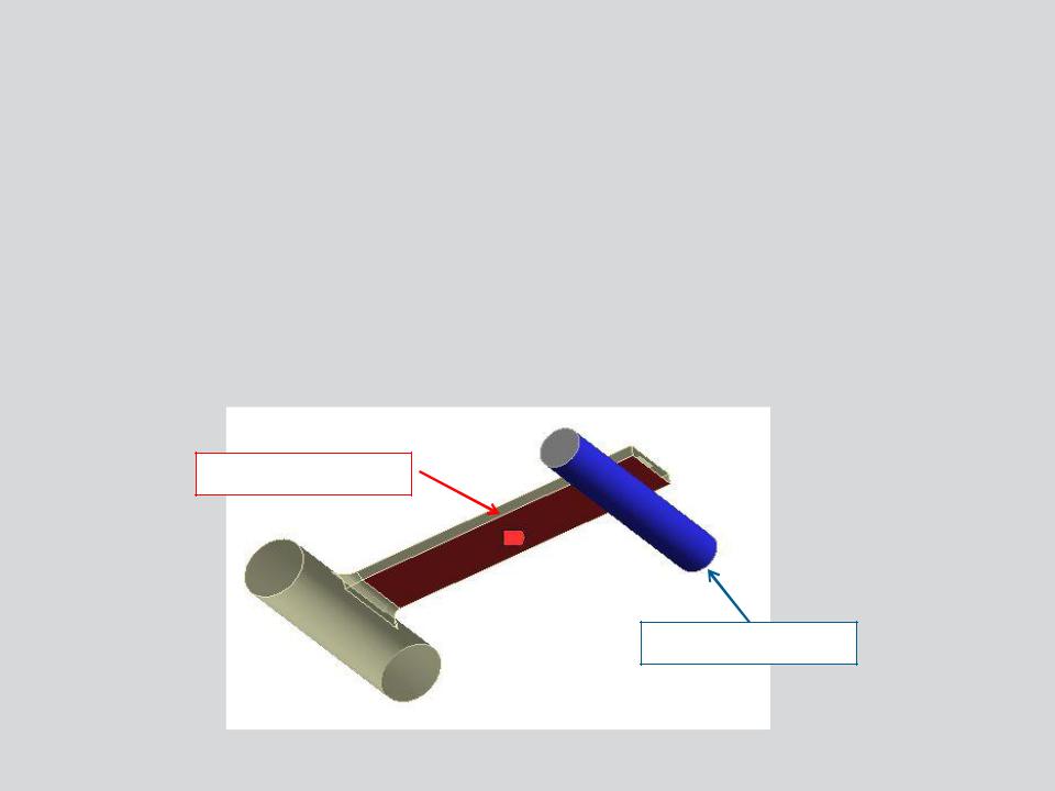
In Mechanical contact pairs are color coded as shown here.
Note, contact is covered in more detail in a later chapter.
Contact Side
Target Side
9 |
© 2012 ANSYS, Inc. |
December 19, 2012 |
Release 14.5 |
 … Contact - Spot Weld
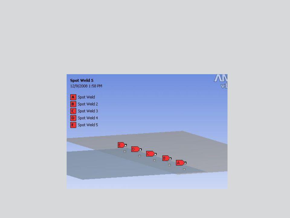
Spot welds provide a means of connecting shell assemblies at discrete points:
•Spotweld definition is done in the CAD software. Currently, only DesignModeler and Unigraphics define supported spot weld definitions.
10 |
© 2012 ANSYS, Inc. |
December 19, 2012 |
Release 14.5 |