

Mechanical_Intro_14.5_L05_Static
.pdf E. Analysis Settings
The “Analysis Settings” details provide general control over the solution process:
Step Controls:
•
•
Manual and auto time stepping controls.
Specify the number of steps in an analysis and an end “time” for each step.
•“Time” is a tracking mechanism in static analyses (discussed later).
Solver Controls:
•Two solvers available (default program chosen):
–Direct solver (Sparse solver in ANSYS).
–Iterative solver (PCG solver in ANSYS).
•Weak springs:
–Mechanical tries to anticipate under-constrained models.
11 |
© 2012 ANSYS, Inc. |
December 19, 2012 |
Release 14.5 |

 . . . Analysis Settings
The “Output Controls” section of the analysis settings configures what items are to be written to the results file (defaults shown).
Output controls are intended to allow users to write efficient results files containing only the desired information thereby limiting file sizes.
The most general results quantities are written by default.
Be sure to review the documentation before starting an analysis to make sure the desired results will be written.
Note: the default configuration for output controls can be changed in “Tools > Options > Analysis Settings and Solution”.
12 |
© 2012 ANSYS, Inc. |
December 19, 2012 |
Release 14.5 |

 F. Loads
Loads and supports respond in terms of the degrees of freedom (DOF) available for the elements used.
With solid geometry the DOF are X, Y and Z translations (for shells and beams we add rotational DOF rotX, rotY and rotZ).
Boundary conditions, regardless of actual names, are always
defined in terms of these DOF. |
UZ |
Boundary conditions can be scoped to geometry items or to |
|
nodes (depending on load type). |
|
Example: a “Frictionless Support” applied to the face of the |
|
block shown would indicate that the Z degree of freedom is |
|
longer free (all other DOF are free). |
|
UY
 UX
UX
Frictionless surface
13 |
© 2012 ANSYS, Inc. |
December 19, 2012 |
Release 14.5 |

 … Loads
Loads and supports having a direction component can be defined in global or local coordinate systems:
•In the Details view, change “Define By” to “Components”. Then, select the appropriate CS from the pull-down menu.
14 |
© 2012 ANSYS, Inc. |
December 19, 2012 |
Release 14.5 |

 … Loads
Acceleration:
•Acts on entire model in length/time2 units.
•Acceleration can be defined by Components or Vector.
•Forces resulting from accelerations act in the opposite direction of the acceleration (e.g. like being pushed back in the seat when an automobile accelerates forward).
Standard Earth Gravity:
•Choose the direction in which the force of gravity acts.
•Value automatically set to current unit system.
•Gravity direction can be defined in global or local coordinate systems.
Rotational velocity:
•Entire model is assumed to rotate about an axis at a given rate.
•Define by vector or component method.
•Input can be in radians per second (default) or RPM.
15 |
© 2012 ANSYS, Inc. |
December 19, 2012 |
Release 14.5 |

 … Loads
Pressure loading:
•
•
•
Applied to nodal groups or surfaces,acts normal to the surface. Positive value into surface, negative value acts out of surface. Units of pressure are in force per area.
Force loading:
•Forces can be applied on nodes, vertices, edges, or surfaces.
•The force will be evenly distributed on all entities. Units are mass*length/time2.
•Force can be defined via vector or component methods.
16 |
© 2012 ANSYS, Inc. |
December 19, 2012 |
Release 14.5 |

 … Loads
Hydrostatic Pressure:
•Applies a linearly varying load to a surface (solid or shell) to simulate fluid force acting on the structure.
•Fluid may be Internal (contained fluid) or external (submerged body).
–User specifies:
•Magnitude and direction of acceleration.
•Fluid Density.
•Free surface location of the fluid.
•For Shells, a Top/Bottom face option is provided.
Internal |
External |
17 |
© 2012 ANSYS, Inc. |
December 19, 2012 |
Release 14.5 |

 … Loads
Bearing Load (force):
•Forces are distributed in compression over the projected area:
–No axial components.
–Use only one bearing load per cylindrical surface.
•If the cylindrical surface is split, select both halves of cylinder when applying the load.
•Bearing loads can be defined via vector or component method.
Bearing Load |
Force Load |
18 |
© 2012 ANSYS, Inc. |
December 19, 2012 |
Release 14.5 |
 … Loads
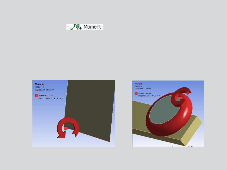
Moment Loading :
•A moment can be applied to a vertex, edge, surface or nodes (named selection).
•If multiple entities are selected, the moment load is evenly distributed.
•Vector or component method can be employed using the right hand rule.
•Units of moment are in Force*length.
19 |
© 2012 ANSYS, Inc. |
December 19, 2012 |
Release 14.5 |

 … Loads
Remote Force Loading :
•Applies an offset force on a vertex, edge, surface or nodes.
•The user supplies the origin of the force (geometry or coordinates).
•Can be defined using vector or component method.
•Applies an equivalent force and moment on the surface.
•Example: 10 inch beam with a 1 lbf remote force scoped to the end of the beam. Remote force is located 20 inches from the fixed support.
F=1 lbf
20” |
Moment Reaction |
|
20 |
© 2012 ANSYS, Inc. |
December 19, 2012 |
Release 14.5 |