

Mechanical_Intro_14.5_L03_GenPrep
.pdfLecture 3
General Preprocessing
14.5 Release
Introduction to ANSYS Mechanical

 Chapter Overview
In this chapter we cover basic preprocessing operations that are common to all disciplines.
Topics:
A.Geometry
B.Contact
C.Workshop 3-1, “2D Gear and Rack Analysis”
D.Coordinate Systems
E.Named Selections
F.Workshop 3-2, “Named Selections”
G.Object Generator
H.Selection Information
I.Workshop 3-3, “Object Generator”
2 |
© 2012 ANSYS, Inc. |
December 19, 2012 |
Release 14.5 |
 A. Geometry
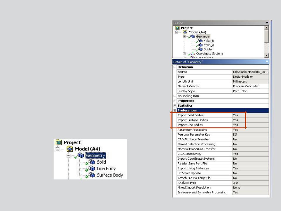
The Geometry branch contains the part(s) that make up the model.
In Mechanical, there are three types of bodies which can be analyzed:
•
•
•
•
Solid bodies are 3D or 2D volumes or areas Surface bodies are only areas
Line bodies are only curves Each is explained next . . .
3 |
© 2012 ANSYS, Inc. |
December 19, 2012 |
Release 14.5 |
 … Geometry
Solid bodies are geometrically and spatially 3D or 2D:
•3D solids are meshed by default with higher-order tetrahedral or hexahedral solid elements with quadratic shape functions.
•2D solids are meshed by default with higher order triangle or quadrilateral solid elements with quadratic shape functions.
– The “2D” switch must be set on the Project page prior to importing geometry.
•Each node has three translational degrees of freedom (DOF) for structural or one temperature DOF for thermal.
|
|
Axisymmetric |
3D Solids |
2D Solids |
cross section |
4 |
© 2012 ANSYS, Inc. |
December 19, 2012 |
Release 14.5 |

 … Geometry
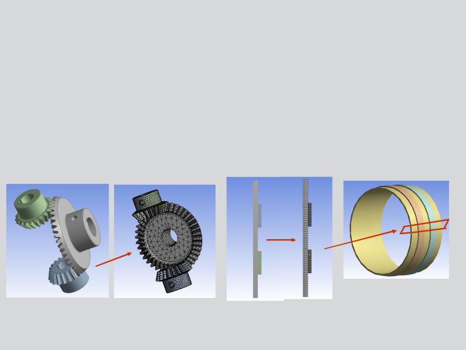
Surface bodies are geometrically2D but spatially 3D:
•Surface bodies represent structures which are thin in one dimension (through the thickness). Thickness is not modeled but supplied as an input value.
•Surface bodies are meshed with linear shell elements having six DOF (UX, UY, UZ, ROTX, ROTY, ROTZ).
Line bodies are geometrically1D but spatially 3D:
•Line bodies represent structures which are thin in two dimensions.The cross-section is not modeled, it is mapped on to the line body.
•Line bodies are modeled with linear beam elements having six DOF (UX, UY, UZ, ROTX, ROTY, ROTZ).
Line Body
Surface Body
5 |
© 2012 ANSYS, Inc. |
December 19, 2012 |
Release 14.5 |

 … Geometry
In general, bodies and parts are the same. In DesignModeler however, multiple bodies may be grouped into multibody parts.
Multibody parts share common boundaries so nodes are shared at that interface.
– No contact is needed in these situations.
Example:
Common nodes are shared by adjacent bodies
6 |
© 2012 ANSYS, Inc. |
December 19, 2012 |
Release 14.5 |
 … Geometry
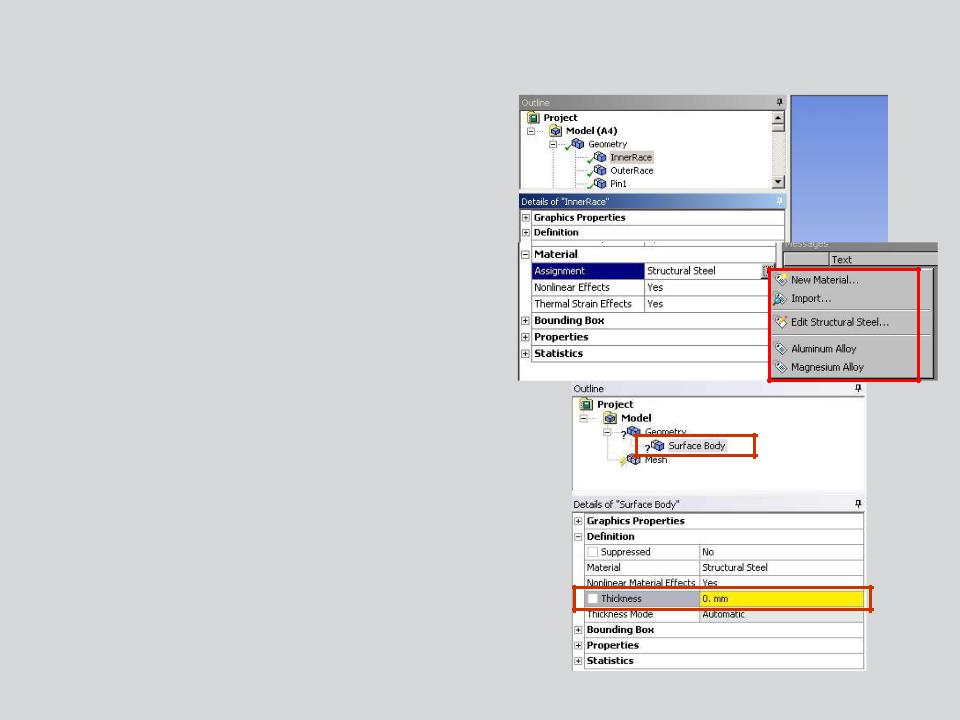
To assign material properties to a part, highlight it and select from the available properties in the “Assignment” field :
•The only materials appearing in the list will be materials added using the “Engineering Data” application (see chapter 2).
•Can also access Engineering Data directly for creating, editing or importing new materials.
For surface bodies a thickness needs to be supplied as well.
7 |
© 2012 ANSYS, Inc. |
December 19, 2012 |
Release 14.5 |

 … Geometry
A summary of all parts along with assigned materials, mesh statistics, etc..
•Select “Geometry” branch and toggle the “Worksheet” icon.
•Toggle between graphics or worksheet via tabs at bottom
8 |
© 2012 ANSYS, Inc. |
December 19, 2012 |
Release 14.5 |
 B. Contact
When multiple parts are present contact elements define the relationship between parts.
• Are parts bonded together, sliding, transferringheat, etc.?
Without contact or spot welds, parts will not interact with each other.
|
|
|
|
|
|
Load |
A |
|
|
|
B |
|
|
|
|
|
|
|
|
|
|
|
|
Contact elements can be visualized as a “skin” covering the regions where contact will occur.
9 |
© 2012 ANSYS, Inc. |
December 19, 2012 |
Release 14.5 |

 … Contact
When an assembly is imported contact surfaces are automatically detected and created:
• The proximity of surfaces is used to detect contact.
•Contact “surfaces” in 2D geometry are represented by edges.
Note, automatic contact should always be verified before proceeding with an analysis. 

Complete coverage of contact is given in lecture 6 “Connections”.
10 |
© 2012 ANSYS, Inc. |
December 19, 2012 |
Release 14.5 |