

Mechanical_Intro_14.5_L03_GenPrep
.pdf … Named Selections
It is often convenient to convert a geometric named selection into a nodal named selection in order to obtain the underlying nodes
•Create a geometry named selection (face for example).
•Create a second named selection using the “Worksheet”.
•Convert the geometry selection to nodes.
Also you can RMB on an existing geometry named selection and “Create Nodal Named Selection”.
21 |
© 2012 ANSYS, Inc. |
December 19, 2012 |
Release 14.5 |

 … Named Selections
Worksheet Summary:
•As can be seen, numerous controls are available in the worksheet. See the documentation for a complete discussion of each.
•As discussed elsewhere in this course the “Convert To” action is used to change a geometry named selection (face, edge, etc.) to a nodal named selection as is done in MAPDL using NSLA, NSLL, etc..
When creating named selections using worksheet criteria a set of tolerances is available if needed:
•Tolerance adjustment is usually only necessary in special circumstances like models in micro units or node selections in dense meshes.
22 |
© 2012 ANSYS, Inc. |
December 19, 2012 |
Release 14.5 |

 F. Workshop 3.2
Workshop 3.2, Named Selections
23 |
© 2012 ANSYS, Inc. |
December 19, 2012 |
Release 14.5 |

 G. Object Generator
The Object Generator uses an existing object in the tree as a template for replication.
Almost any tree object that supports “RMB > Duplicate” can be used as a template.
An example:
In the model shown, we have set up a mesh size control on one of the hole faces. We would like to have this same control applied to all other holes.
24 |
© 2012 ANSYS, Inc. |
December 19, 2012 |
Release 14.5 |

 . . . Object Generator
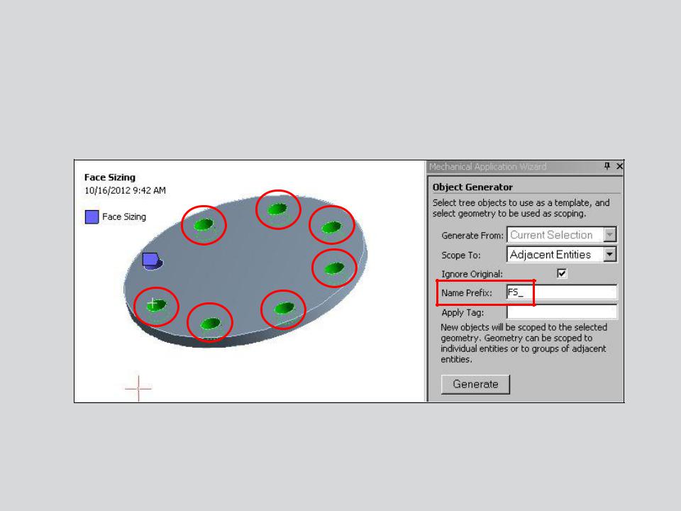
Highlight the tree object to be replicated (the Face Sizing in this case) and activate the Object Generator using the icon.
The object generator opens and indicates objects will be generated from the “Current Selection”
(graphical selection) or from a named selection we’ve called “Top Holes”.
25 |
© 2012 ANSYS, Inc. |
December 19, 2012 |
Release 14.5 |
 . . . Object Generator
We choose to graphically highlight the remaining hole faces and add a Name
Prefix (“FS_”) so the new objects can be easily identified in the tree.
26 |
© 2012 ANSYS, Inc. |
December 19, 2012 |
Release 14.5 |

 . . . Object Generator
After generating, the new objects can be displayed graphically and they appear in the tree. The object names reflect that of the parent object along with the prefix chosen (if any).
In this example the object to be generated (the mesh size control) required only a single geometry selection, a face, to define its scope. Some objects that can be duplicated require multiple scoping selections (e.g. contacts, beam connections, etc.). We’ll look at this next.
27 |
© 2012 ANSYS, Inc. |
December 19, 2012 |
Release 14.5 |

 . . . Object Generator
When an object in the tree that requires multiple scoping is selected, the object generator reflects this (a contact selection is shown here).
•Fields for contact and target scoping are visible however there is no longer a “current selection” choice. Instead, named selections must now be chosen from the drop down fields.
•A “Distance Between Centroids” range must now be set to indicate which parts of the named selections are to be paired to one another.
•In addition to an optional prefix, new items can be tagged when generated.
28 |
© 2012 ANSYS, Inc. |
December 19, 2012 |
Release 14.5 |

. . . Object Generator
Here a bolt connection has been defined between the plates and named selections created for the holes in each plate. The range chosen is based on the distance between the plates (20 mm).
29 |
© 2012 ANSYS, Inc. |
December 19, 2012 |
Release 14.5 |

. . . Object Generator
Scoping the new objects:
Pressure load generated to 2 selected surfaces.
“Adjacent” (default) distributes the scope to all selections.
“Each” creates a new object for each selection.
30 |
© 2012 ANSYS, Inc. |
December 19, 2012 |
Release 14.5 |