

Mechanical_Intro_14.5_L02_Basics
.pdfLecture 2
Mechanical Basics
14.5 Release
Introduction to ANSYS Mechanical

 Chapter Overview
In this chapter we introduce the basic features in Mechanical :
A.Basic Analysis Procedure
B.The Mechanical Interface
C.Menus
D.Toolbars
E.Graphics Control and Selection
F.Outline Tree and Details
G.Tagging and Tree Filtering
H.Graphics Window
I.The Mechanical Application Wizard
J.Scoping Loads and Supports
K.The Engineering Data application
L.Assigning Material Properties
M.Workshop 2-1
2 |
© 2012 ANSYS, Inc. |
December 19, 2012 |
Release 14.5 |

 A. Basic Analysis Procedure
A finite element analysis is used to determine the response of a system based on some type of loading.
It is important to remember that a finite element solution is an approximation:
•CAD geometry is an idealization of the physical model.
•The mesh is a combination of discreet “elements” representing the geometry.
•The accuracy of answers is determined by various factors, one of which is the mesh density.
CAD Model |
|
Finite Element Mesh |
|
|
|
3 |
© 2012 ANSYS, Inc. |
December 19, 2012 |
Release 14.5 |
 … Basic Analysis Procedure
An analysis can be described in the context of four main steps:
• PreliminaryDecisions
– What type of analysis: Static, modal, etc.?
–What to model: Part or Assembly?
–Which elements: Surface or Solid Bodies?
–Should I start with a simpler model?
–Symmetry?
•Preprocessing
–Attach the model geometry
–Define and assign material properties to parts
–Mesh the geometry
–Apply loads and supports
–Request results
•Solve the Model
•Postprocessing
–Review results
–Check the validity of the solution
4 |
© 2012 ANSYS, Inc. |
December 19, 2012 |
Release 14.5 |
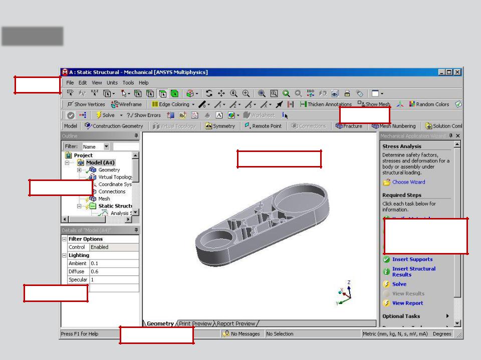
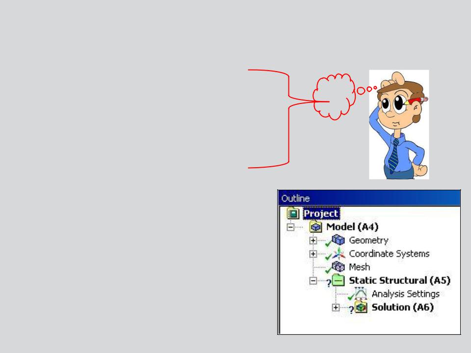
 B. The Mechanical Interface
The components of the user interface are shown below:
Menus |
Toolbars
Graphics Window
Outline Tree
Mechanical
Application Wizard
Details View
Status Bar
5 |
© 2012 ANSYS, Inc. |
December 19, 2012 |
Release 14.5 |
 . . . The Mechanical Interface
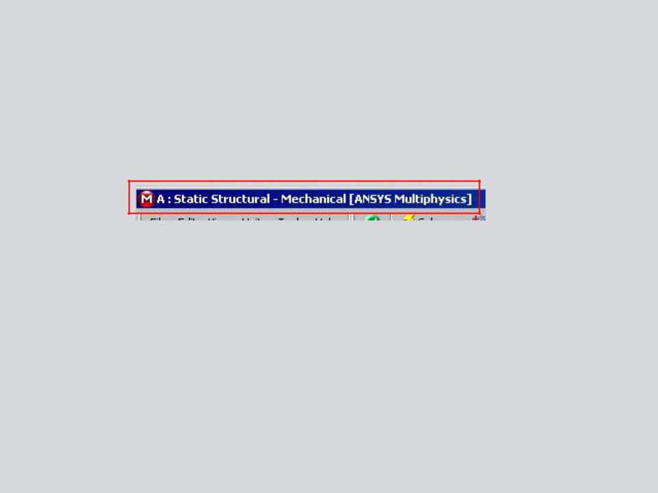
A range of menus and toolbars provide much of the general functionality in Mechanical.
• The title bar lists analysis type, product and active ANSYS license.
Some menu and toolbar items are self explanatory. We’ll cover the basic controls on the next few slides.
•Additional controls and features will be introduced throughout the course as they are encountered.
Note: the windows in Workbench and the Mechanical application can be customized. If you wish to return to a default layout use in either:
Mechanical: “View > Windows > Layout > Reset Window Layout”.
Workbench: “View > Reset Window Layout”.
6 |
© 2012 ANSYS, Inc. |
December 19, 2012 |
Release 14.5 |
 C. Menus
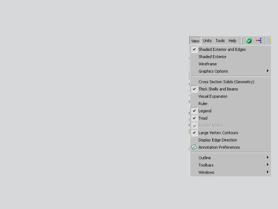
The View menu:
•Control basic graphics (shaded, wireframe,etc.).
•Control graphical expansion of shells and beams.
•Control display utilities (legend, triad, ruler, etc.).
•Set preferences for annotation display.
•Select the desired toolbars and windows to be displayed.
7 |
© 2012 ANSYS, Inc. |
December 19, 2012 |
Release 14.5 |

 . . . Menus
Annotation Preferences:
•Controls the display of annotations for loads/constraints, user labels, remote conditions and meshing displays.
•Make preference selections then “Apply” or “OK” to reflect the changes.
8 |
© 2012 ANSYS, Inc. |
December 19, 2012 |
Release 14.5 |
 . . . Menus
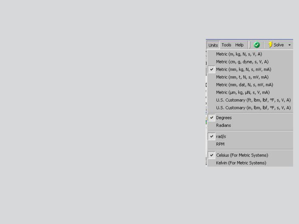
The Units menu:
•Specify the unit system for Mechanical.
•Note, Mechanical may use any unit system regardless of the one specified in Workbench. Where needed, automatic conversions will be made.
•Mechanical will “remember” the units used in the previous session (regardless of the units set in Workbench).
•Specify additional units for angular, rotational and thermal
references.
9 |
© 2012 ANSYS, Inc. |
December 19, 2012 |
Release 14.5 |

 D. Toolbars
The “Standard” toolbar is shown below (details will be covered later):
A |
|
B |
|
|
|
|
|
|
|
F |
|
|
C |
|
D |
|
E |
|
A.Activate the Mechanical Wizard.
B.Solve
C.Create slice planes, annotations, charts and tables.
D.Add comments and figures to the tree.
E.Activate optional Worksheet view.
F.Activate selection information window.
10 |
© 2012 ANSYS, Inc. |
December 19, 2012 |
Release 14.5 |