

Mechanical_Intro_14.5_L10_Thermal
.pdfLecture 10
Thermal Analysis
14.5 Release
Introduction to ANSYS Mechanical

 Chapter Overview
In this chapter, performing steady-state thermal analyses in Mechanical will be covered:
A.Basics of Steady State Heat Transfer
B.Geometry
C.Material Properties
D.Thermal Contact
E.Thermal Boundary Conditions
F.Solution Options
G.Results and Postprocessing
H.Workshop 10.1 – Pump Housing
Note: advanced topics including thermal transient analyses are covered in the ANSYS Mechanical Heat Transfer training course.
2 |
© 2012 ANSYS, Inc. |
December 19, 2012 |
Release 14.5 |

 A. Basics of Steady-State Heat Transfer
The schematic setup for a steady-state (static) thermal analysis is shown here.
Later in this chapter we will shown the procedure for setting up a coupled thermal structural analysis.
3 |
© 2012 ANSYS, Inc. |
December 19, 2012 |
Release 14.5 |

 . . . Basics of Steady-State Heat Transfer
For a steady-state (static) thermal analysis in Mechanical, the temperatures {T} are solved for in the matrix below:
K T T Q T
Assumptions:
•No transient effects are considered in a steady-state analysis
•[K] can be constant or a function of temperature
•{Q} can be constant or a function of temperature
•Fixed temperatures represent constraints {T} on the system (like fixed displacements on structures).
It is important to remember these assumptions related to performing thermal analyses in Mechanical.
4 |
© 2012 ANSYS, Inc. |
December 19, 2012 |
Release 14.5 |

 B. Geometry
In thermal analyses all body types are supported:
•Solid, surface, and line bodies.
–Line bodies cross-section and orientation is defined within DesignModeler.
–A “Thermal Mass” feature is available for use in transient analysis (not covered in this course).
Shell and line body assumptions:
•Shells: temperatures may vary over the surface (no through-thickness temperature variation).
•Line bodies: temperature may vary along the length of the beam (no variation across the cross section).
5 |
© 2012 ANSYS, Inc. |
December 19, 2012 |
Release 14.5 |
 C. Material Properties
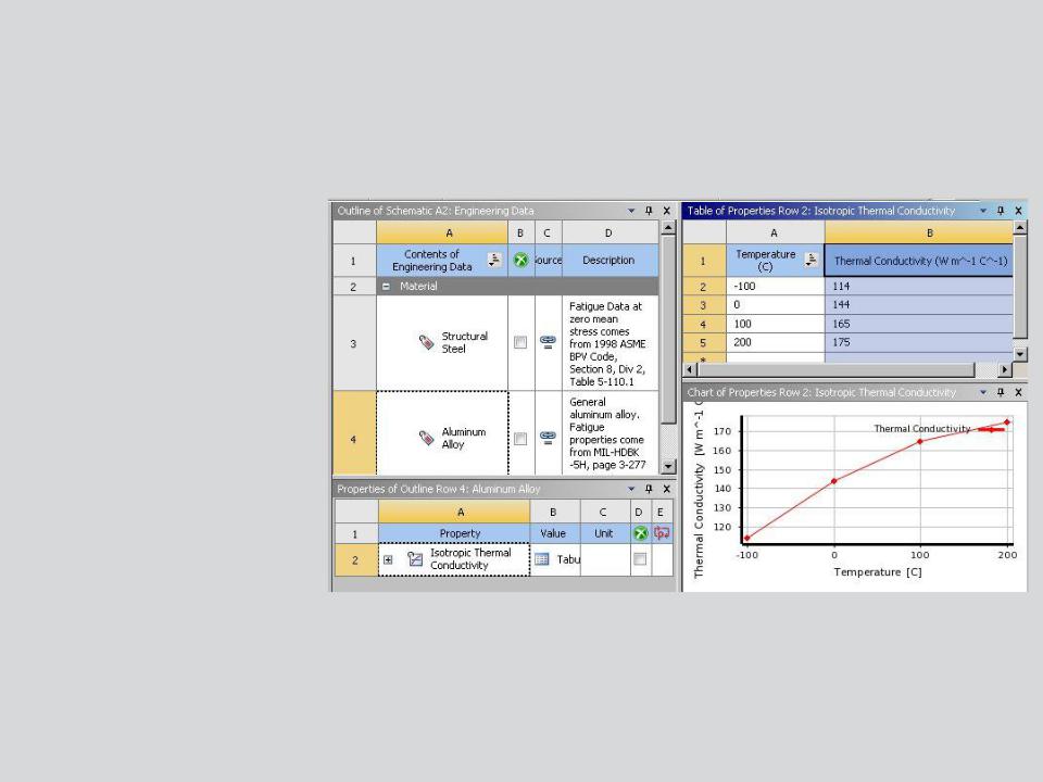
•The only required material property for steady state is thermal conductivity.
•Thermal Conductivity is input in the Engineering Data application
•Temperature-dependent thermal conductivity is input as a table
6 |
© 2012 ANSYS, Inc. |
December 19, 2012 |
Release 14.5 |

 D. Thermal Contact
As with structural analyses, contact regions are automatically created to enable heat transfer between parts in assemblies.
7 |
© 2012 ANSYS, Inc. |
December 19, 2012 |
Release 14.5 |


 … Thermal Contact
• When can heat flow across a contact region?
|
Contact Type |
Heat Transfer Between Parts in Contact Region? |
|
|||
|
Initially Touching |
Inside Pinball Region |
Outside Pinball Region |
|||
|
|
|
||||
|
Bonded |
Yes |
Yes |
No |
||
|
|
|
|
z |
|
|
|
No Separation |
|
Yes |
No |
|
|
|
Yes |
|||||
|
Rough |
|
Yes |
No |
No |
|
|
Frictionless |
|
Yes |
No |
No |
|
|
Frictional |
Yes |
No |
No |
||
|
|
|
|
|
|
|
•Thermal Contact Behavior:
–If parts are in contact heat transfer can occur between them.
–If parts are out of contact no heat transfer takes place.
•For bonded and no separation the pinball can be expanded to allow heat transfer across a gap.
8 |
© 2012 ANSYS, Inc. |
December 19, 2012 |
Release 14.5 |

 … Thermal Contact
If the contact is bonded or no separation, then heat transfer will occur when the surfaces are within the pinball radius.
Pinball Radius
In this figure, the gap between the two parts is larger than the pinball region, so no heat transfer will occur between the parts.
9 |
© 2012 ANSYS, Inc. |
December 19, 2012 |
Release 14.5 |
 … Thermal Contact
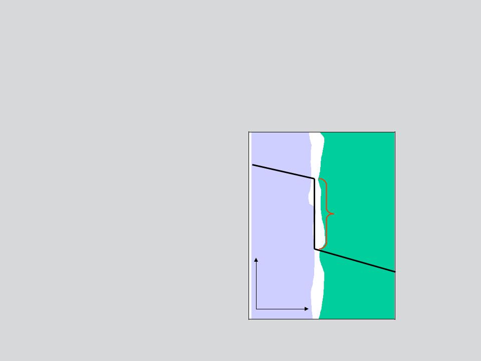
By default, perfect thermal contact is assumed, meaning no temperature drop occurs at the interface.
Numerous “real world” conditions can contribute to less than perfect contact conductance:
•Surface roughness
•surface finish
•Oxides
•trapped fluids
•contact pressure
•surface temperature
•lubricants
•Etc . . . .
Continued . . .
T |
T |
x |
10 |
© 2012 ANSYS, Inc. |
December 19, 2012 |
Release 14.5 |