


151781-1CD
5.1 Basic Specifications
HP600 MANIPULATOR
5 Basic Specifications
5.1Basic Specifications
|
|
Table. 2 Basic Specifications*1 |
|
|
|
|
|
Item |
|
Model |
MOTOMAN-UP350N-600 |
|
(YR-UP350N-A30, -A31) |
||
|
|
|
|
|
|
|
|
|
Operation Mode |
Vertically Articulated |
|
|
|
||
Degree of Freedom |
6 |
||
|
|
|
|
|
|
Payload |
600 kg |
|
|
||
Repetitive Positioning Accuracy*2 |
±0.5 mm |
||
|
|
S-Axis (turning) |
±150° |
|
|
|
|
|
|
L-Axis (lower arm) |
+61°, -55° |
|
|
|
|
Motion |
|
U-Axis (upper arm) |
+30°, -113° |
Range |
|
|
|
|
R-Axis (wrist roll) |
±360° |
|
|
|
|
|
|
|
B-Axis (wrist pitch/yaw) |
±125° |
|
|
|
|
|
|
T-Axis (wrist twist) |
±360° |
|
|
|
|
|
|
S-Axis |
1.05 rad/s, 60°/s |
|
|
|
|
|
|
L-Axis |
1.22 rad/s, 70°/s |
|
|
|
|
Maximum |
|
U-Axis |
1.22 rad/s, 70°/s |
Speed |
|
|
|
|
R-Axis |
1.40 rad/s, 80°/s |
|
|
|
|
|
|
|
B-Axis |
1.40 rad/s, 80°/s |
|
|
|
|
|
|
T-Axis |
2.79 rad/s, 160°/s |
|
|
|
|
Allowable |
|
R-Axis |
2450 N•m (250 kgf•m) |
|
|
|
|
|
B-Axis |
2450 N•m (250 kgf•m) |
|
Moment |
|
||
|
|
|
|
|
|
T-Axis |
823 N•m (84 kgf•m) |
|
|
|
|
Allowable |
|
R-Axis |
200 kg•m2 |
|
|
|
|
Inertia*3 |
|
B-Axis |
200 kg•m2 |
(GD2/4) |
|
|
|
|
T-Axis |
90 kg•m2 |
|
|
|
||
|
|
Mass |
2400 kg |
|
|
|
|
|
|
Temperature |
0 to 45°C |
|
|
|
|
|
|
Humidity |
20 to 80% RH (non-condensing) |
Ambient |
|
|
|
|
Vibration acceleration |
4.9 m/s2 (0.5G) or less |
|
Conditions |
|
||
|
|
|
|
|
|
|
• Free from corrosive gasses or liquids, or explosive gasses |
|
|
Others |
• Clean and dry |
|
|
|
• Free from excessive electrical noise (plasma) |
|
|
|
|
|
Power Capacity |
10.0 kVA |
|
|
|
|
|
*1
*2
*3
SI units are used in this table. However, gravitational unit is used in (). Conformed to ISO9283.
Refer to " 6.1 Allowable Wrist Load " for details on the permissible moment of inertia.
5-1
HW0482904 24/73

151781-1CD
5.2 Part Names and Working Axes
HP600 MANIPULATOR
5.2Part Names and Working Axes
Upper arm |
|
|
|
|
|
(U-arm) |
U+ |
|
|
Wrist |
T+ |
|
R+ |
B+ |
|||
|
|
||||
|
|
|
|
|
Writ flange |
|
U- |
R- |
B- |
|
T- |
L- |
L+ |
|
|
|
|
Lower arm
S+ (L-arm)
Rotary head
(S-head)
S-
Base
Fig. 8 Part Names and Working Axes
5.3Manipulator Base Dimensions
90 860
405±0.3
760
640
|
|
|
±0.3 |
394 |
|
|
|
|
355 |
|
|
|
12 dia. |
+ 0.018 |
hole |
405±0.3 |
|
A |
0 |
|
|
||
(2 places) |
|
|
View A |
||
|
|
|
|
|
|
Fig. 9 Manipulator Base Dimensions
5-2
28 dia. hole (8 places)
|
|
|
|
|
|
|
|
|
|
|
|
|
|
±0.3 |
|
|
|
|
|
|
|
|
|
|
|
|
|
||
|
|
|
|
|
|
|
|
||
|
|
|
|
|
|
|
|
||
|
|
|
|
|
|
|
|
||
|
|
|
|
355 |
|
760 |
860 |
||
|
|
|
|
|
|
|
|||
|
|
640 |
|
|
|
||||
|
|
|
|
|
|
|
|
|
|
|
|
|
|
|
|
|
|
|
|
|
|
|
|
|
|
|
|
|
|
|
|
|
|
|
|
|
|
|
|
|
|
|
|
|
|
|
|
|
|
Units: mm
HW0482904 25/73
151781-1CD
5.4 Dimensions and P-Point Maximum Envelope
HP600 MANIPULATOR
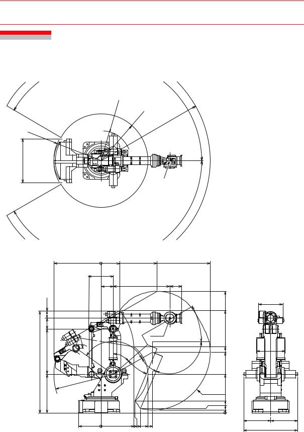
5.4Dimensions and P-Point Maximum Envelope
R698
R1098
1020
|
1099 |
0 |
|
|
575 |
|
|
280 |
|
165 |
|
|
250 |
|
|
30 |
° |
|
° |
55 |
2365 |
1050 |
|
|
R1378 |
|
|
900 |
|
525 |
0 |
R1084 |
R2542 |
|
150
°
P-point
° 150
439 |
1299 |
2542 |
|
1320 |
270 |
|
|
|
|
2827 |
|
|
|
|
|
|
565.5 |
|
|
|
|
2379 |
|
|
|
|
30 |
|
|
|
|
|
° |
|
|
|
|
P-point |
|
|
|
61 |
|
|
|
|
|
° |
|
|
|
1543 |
661 |
|
|
|
|
||
49 |
|
|
|
1410 |
|
|
|
|
|
|
|
° |
|
|
|
|
|
26 |
|
38 |
° |
|
|
|
|
|
|
||
° |
|
° |
113 |
|
|
|
|
|
900 |
|
|
|
|
|
|
|
|
|
|
|
P-point maximum |
|
|
|
|
|
envelope |
277 |
|
|
|
|
|
97 |
|
|
|
|
|
66 |
|
|
|
|
|
0 |
624 |
|
|
|
|
624 |
|
763 787 913 |
1084 |
1199 |
|
|
1248 |
|
|
Units: mm |
|||
|
|
|
|
|
Fig. 10 External Dimensions and P-Point Maximum Envelope
5-3
HW0482904 26/73

151781-1CD
5.5 Alterable S-axis Operating Range
HP600 MANIPULATOR
5.5Alterable S-axis Operating Range
The operating range of the S-axis can be altered according to the operating conditions as shown in " Table. 3 S-axis Operating Range ". If alteration is necessary, contact your Yaskawa representative in advance.
Table. 3 S-axis Operating Range
Item |
Specifications |
S-axis |
±150° (standard) |
±120° |
|
Operating |
± 90° |
Range |
± 60° |
|
± 30° |
5-4
HW0482904 27/73