


151781-1CD
9.2 Notes on Maintenance Procedures
HP600 MANIPULATOR
9.2Notes on Maintenance Procedures
9.2.1Battery Pack Replacement
The battery packs are attached in the two locations shown in " Fig. 18 Location of Battery Packs ".
Battery pack (HW0470360-A)
Board
Base
|
AIR |
4BC |
|
|
2BC |
3BC |
|
|
1BC |
|
|
|
A |
|
|
Plate |
Plate fastnening bolt M4 |
Connector base |
|
Fig. 18 Location of Battery Packs
9-6
HW0482904 40/73
151781-1CD
9.2 Notes on Maintenance Procedures
HP600 MANIPULATOR
Battery pack before replacement
See step 5 below.
Connector |
Board
See step 4 below.
Fig. 19 Battery Connections
New battery pack
(HW0470360-A)
If the battery alarm occurs in the NX100, replace the battery pack according to the following procedure:
1.Turn OFF the NX100 main power supply.
2.Remove the plate from the connector base and pull the battery pack out to replace with a new battery pack.
3.Remove the battery pack from the battery holder.
4.Connect the new battery pack to the unoccupied connector on the board.
5.Remove the old battery pack from the board.
NOTE Remove the old battery pack after connecting the new one so that the encoder absolute data does not disappear.
6.Mount the new battery pack to the battery holder.
7.Reinstall the plate with screws.
NOTE Do not pinch the cable when the plate is installed.
9-7
HW0482904 41/73

151781-1CD
9.2 Notes on Maintenance Procedures
HP600 MANIPULATOR
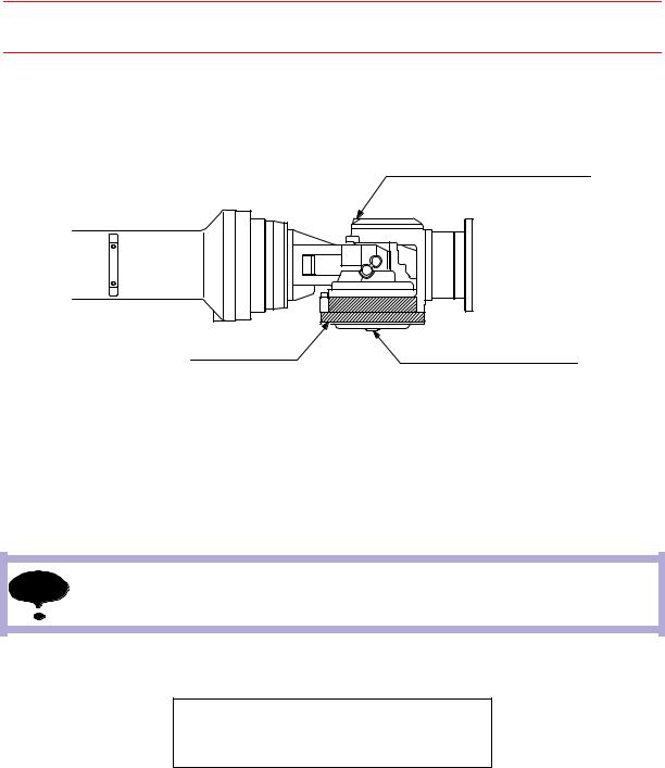
9.2.2Grease Replenishment/Exchange for S-axis Speed Reducer
Grease exhaust port
Hexagon socket head plug PT1/4
Grease inlet
Hexagon socket head plug PT1/4
S-axis speed reducer |
Fig. 20 S-axis Speed Reducer and Gear Diagram
Grease Replenishment (Refer to " Fig. 20 S-axis Speed Reducer and Gear Diagram ".)
1.Remove the hexagon socket head plugs PT1/4 from the grease inlet and grease exhaust port.
NOTE If grease is added with the plug on, the grease will go inside the motor and may damage it. Make sure to remove the plug without fail.
2.Install the grease zerk A-PT1/4 to the grease inlet and inject the grease using a grease gun. (The grease zerk A-PT1/4 is delivered with the manipulator.)
Grease type: Molywhite RE No.00 Amount of grease: 750cc (1500cc for the 1st supply)
3.Move the S-axis for a few minute to discharge excess grease.
4.Remove the grease zerk and reinstall the plug PT1/4 to the grease inlet. Tighten the plug with a tightening torque of 4.9 N•m (0.5 kgf•m). (Apply Three Bond 1206C on the thread part of plug.)
5.Wipe the grease exhaust port with a cloth and reinstall the plug PT1/4 to the grease exhaust port. Tighten the plug with a tightening torque of 4.9 N•m (0.5 kgf•m). (Apply Three Bond 1206C on the thread part of plug.)
9-8
HW0482904 42/73

151781-1CD
9.2 Notes on Maintenance Procedures
HP600 MANIPULATOR
Grease Exchange (Refer to " Fig. 20 S-axis Speed Reducer and Gear Diagram ".)
1.Remove the hexagon socket head plugs PT1/4 from the grease inlet and grease exhaust port.
NOTE If grease is added with the plug on, the grease will go inside the motor and may damage it. Make sure to remove the plug without fail.
2.Install the grease zerk A-PT1/4 to the grease inlet and inject the grease using a grease gun. (The grease zerk A-PT1/4 is delivered with the manipulator.)
Grease type: Molywhite RE No.00
Amount of grease: 2500cc
3.The grease exchange is completed when new grease appears in the grease exhaust port. The new grease can be distinguished from the old grease by color.
4.Move the S-axis for a few minutes to discharge excess grease.
5.Wipe the grease exhaust port with a cloth and reinstall the plug PT1/4. Tighten the plug with a tightening torque of 4.9 N•m (0.5 kgf•m). (Apply Three Bond 1206C on the thread part of plug.)
6.Remove the grease zerk from the grease inlet and reinstall the plug PT1/4. Tighten the plug with a tightening torque of 4.9 N•m (0.5 kgf•m). (Apply Three Bond 1206C on the thread part of plug.)
If the plugs are reinstalled while the grease is being discharged, the grease will go inside NOTE the motor and may damage it. Make sure that the grease discharge is completed before
installing the plugs.
9-9
HW0482904 43/73

151781-1CD
9.2 Notes on Maintenance Procedures
HP600 MANIPULATOR
9.2.3Grease Replenishment/Exchange for L- and U-axes Speed Reducers
|
|
|
|
|
|
|
|
|
|
|
|
|
|
|
|
|
|
|
|
|
|
|
|
|
|
|
|
|
|
|
|
|
|
|
|
|
|
|
|
|
|
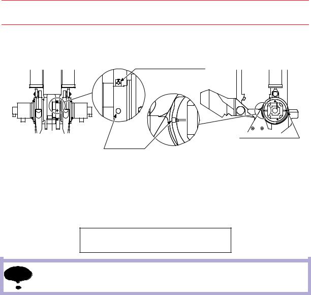
Grease exhaust port |
|||||||||||||||||
Grease exhaust port at L-axis speed reducer |
|
|
|
|
|
|
|
|
|
|
|
|
|
|
|
|
|
|
|
at U-axis speed reducer |
|
||||||||||||||||||||||||||||||||||||||
Air breather |
|
|
|
|
|
|
|
|
|
|
|
|
|
|
|
|
|
|
|
Hexagon socket head plug PT1/8 |
|||||||||||||||||||||||||||||||||||||||
|
|
|
|
|
|
|
|
|
|
|
|
|
|
|
|
|
|
|
|
|
|
|
|
|
|
|
|
|
|
|
|
|
|
|
|
|
|
|
|
|
|
|
|
|
|
|
|
|
|
|
|
|
|
|
|
|
|
|
|
|
|
|
|
|
|
|
|
|
|
|
|
|
|
|
|
|
|
|
|
|
|
|
|
|
|
|
|
|
|
|
|
|
|
|
|
|
|
|
|
|
|
|
|
|
|
|
|
|
|
|
|
|
|
|
|
|
|
|
|
|
|
|
|
|
|
|
|
|
|
|
|
|
|
|
|
|
|
|
|
|
|
|
|
|
|
|
|
|
|
|
|
|
|
|
|
|
|
|
|
|
|
|
|
|
|
|
|
|
|
|
|
|
|
|
|
|
|
|
|
|
|
|
|
|
|
|
|
|
|
|
|
|
|
|
|
|
|
|
|
|
|
|
|
|
|
|
|
|
|
|
|
|
|
|
|
|
|
|
|
|
|
|
|
|
|
|
|
|
|
|
|
|
|
|
|
|
|
|
|
|
|
|
|
|
|
|
|
|
|
|
|
|
|
|
|
|
|
|
|
|
|
|
|
|
|
|
|
|
|
|
|
|
|
|
|
|
|
|
|
|
|
|
|
|
|
|
|
|
|
|
|
|
|
|
|
|
|
|
|
|
|
|
|
|
|
|
|
|
|
|
|
|
|
|
|
|
|
|
|
|
|
|
|
|
|
|
|
|
|
|
|
|
|
|
|
|
|
|
|
|
|
|
|
|
|
|
|
|
|
|
|
|
|
|
|
|
|
|
|
|
|
|
|
|
|
|
|
|
|
|
|
|
|
|
|
|
|
|
|
|
|
|
|
|
|
|
|
|
|
|
|
|
|
|
|
|
|
|
|
|
|
|
|
|
|
|
|
|
|
|
|
|
|
|
|
|
|
|
|
Grease inlet at |
|
Grease inlet at |
||||
|
U-axis speed reducer |
|||||
L-axis speed reducer |
|
|||||
|
Hexagon socket head plug PT1/8 |
|||||
Hexagon socket head plug PT1/8 |
|
|||||
|
|
|
|
|||
|
L-axis speed reducer |
|
|
|
U-axis speed reducer |
|
|
|
|
|
|
|
|
Fig. 21 LU-axis Speed Reducer Diagram
Grease Replenishment (Refer to " Fig. 21 LU-axis Speed Reducer Diagram ".)
1.For L-axis, remove the hexagon socket head plug PT1/8 and air breather from the grease inlet and grease exhaust port. For U-axis, remove the hexagon socket head plugs PT1/8 from the grease inlet and grease exhaust port.
NOTE If grease is added with the plug/air breather on, the grease will go inside the motor and may damage it. Make sure to remove the plug/air breather without fail.
2.Install the grease zerk A-PT1/8 to the grease inlet and inject the grease into the grease inlet using a grease gun. (The grease zerk A-PT1/8 is delivered with the manipulator.)
Grease type: Molywhite RE No.00 Amount of grease: 600cc (1200cc for the 1st supply)
3.Move the L-axis/U-axis for a few minutes to discharge excess grease.
4.For the L-axis, wipe the grease exhaust port with a cloth and reinstall the air breather. For the U-axis, wipe the grease exhaust port with a cloth and reinstall the plug. Tighten the plug with a tightening torque of 4.9 N•m (0.5 kgf•m). (Apply Three Bond 1206C on the thread part of plug.)
5.Remove the grease zerk from grease inlet and reinstall the plug. Tighten the plug with a tightening torque of 4.9 N•m (0.5 kgf•m). (Apply Three Bond 1206C on the thread part of plug.)
9-10
HW0482904 44/73

151781-1CD
9.2 Notes on Maintenance Procedures
HP600 MANIPULATOR
Grease Exchange (Refer to " Fig. 21 LU-axis Speed Reducer Diagram ".)
1.For L-axis, remove the hexagon socket head plug PT1/8 and air breather from the grease inlet and grease exhaust port. For U-axis, remove the hexagon socket head plugs PT1/8 from the grease inlet and grease exhaust port.
NOTE If grease is added with the plug/air breather on, the grease will go inside the motor and may damage it. Make sure to remove the plug/air breather without fail.
2.Install the grease zerk A-PT1/8 to the grease inlet and inject the grease into the grease inlet using a grease gun. (The grease zerk A-PT1/8 is delivered with the manipulator.)
Grease type: Molywhite RE No.00
Amount of grease: approx. 1800cc
3.The grease exchange is completed when new grease appears in the grease exhaust port. The new grease can be distinguished from the old grease by color.
4.Move the L-axis/U-axis for a few minutes to discharge excess grease.
5.For the L-axis, wipe the grease exhaust port with a cloth and reinstall the air breather. For the U-axis, wipe the grease exhaust port with a cloth and reinstall the hexagon socket head plug PT1/8. Tighten the plug with a tightening torque of 4.9 N•m (0.5 kgf•m). (Apply Three Bond 1206C on the thread part of plug.)
6.Remove the grease zerk from the grease inlet and reinstall the plug. Tighten the plug with a tightening torque of 4.9 N•m (0.5 kgf•m). (Apply Three Bond 1206C on the thread part of plug.)
9-11
HW0482904 45/73

151781-1CD
9.2 Notes on Maintenance Procedures
HP600 MANIPULATOR
9.2.4Grease Replenishment/Exchange for R-axis Speed Reducer
R-axis speed reducer
Grease inlet
Hexagon socket head plug PT1/8
Grease exhaust port
Hexagon socket head plug PT1/8
Fig. 22 R-axis Speed Reducer Diagram
Grease Replenishment (Refer to " Fig. 22 R-axis Speed Reducer Diagram ".)
1.Remove the hexagon socket head plug PT1/8 from the grease inlet
2.Remove the cap so that the hexagon socket head plug PT1/8 behind the cap can be uninstalled.
NOTE If grease is added with the plug on, the grease will go outside the grease box and may damage it. Make sure to remove the plug without fail.
3.Install the grease zerk A-PT1/8 to the grease inlet and inject the grease using a grease gun. (The grease zerk A-PT1/8 is delivered with the manipulator.)
Grease type: Molywhite RE No.00 Amount of grease: 700cc (1400cc for the 1st supply)
4.Move the R-axis for a few minutes to discharge excess grease.
5.Wipe the grease exhaust port with a cloth and reinstall the plug. Tighten the plug with a tightening torque of 4.9 N•m (0.5 kgf•m). (Apply Three Bond 1206C on the thread part of plug.)
6.Remove the grease zerk from the grease inlet and reinstall the plug. Tighten the plug with a tightening torque of 4.9 N•m (0.5 kgf•m). (Apply Three Bond 1206C on the thread part of plug.)
7.Reinstall the cap back into place.
9-12
HW0482904 46/73

151781-1CD
9.2 Notes on Maintenance Procedures
HP600 MANIPULATOR
Grease Exchange (Refer to " Fig. 22 R-axis Speed Reducer Diagram ".)
1.Remove the hexagon socket head plug PT1/8 from the grease inlet.
2.Remove the cap so that the hexagon socket head plug PT1/8 behind the cap can be uninstalled.
NOTE If grease is added with the plug on, the grease will go outside the grease box and may damage it. Make sure to remove the plug without fail.
3.Install the grease zerk A-PT1/8 to the grease inlet and inject the grease using a grease gun. (The grease zerk A-PT1/8 is delivered with the manipulator.)
Grease type: Molywhite RE No.00
Amount of grease: 3200cc
4.The grease exchange is completed when new grease appears in the grease exhaust port. The new grease can be distinguished from the old grease by color.
5.Move the R-axis for a few minutes to discharge excess grease.
6.Wipe the grease exhaust port with a cloth and reinstall the plug. Tighten the plug with a tightening torque of 4.9 N•m (0.5 kgf•m). (Apply Three Bond 1206C on the thread part of plug.)
7.Remove the grease zerk from the grease inlet and reinstall the plug. Tighten the plug with a tightening torque of 4.9 N•m (0.5 kgf•m). (Apply Three Bond 1206C on the thread part of plug.)
8.Reinstall the cap back into place.
9-13
HW0482904 47/73
151781-1CD
9.2 Notes on Maintenance Procedures
HP600 MANIPULATOR
9.2.5Grease Replenishment/Exchange for B-axis Speed Reducer and Gear
Grease exhaust port
Hexagon socket head cap screw M6X8 (DACROTIZED coating)
B-axis speed reducer |
Grease inlet |
|
|
|
Hexagon socket head plug PT1/8 |
Fig. 23 B-axis Speed Reducer and Gear Diagram
Grease Replenishment (Refer to " Fig. 23 B-axis Speed Reducer and Gear Diagram ".)
1.Remove the hexagon socket head plug PT1/8 from the grease inlet.
2.Remove the hexagon socket head cap screw M6X8 (DACROTIZED coating) from the grease exhaust port.
NOTE If grease is added with the screw on, the grease will go outside the grease box and may damage it. Make sure to remove the screw without fail.
3.Install the grease zerk A-PT1/8 to the grease inlet and inject the grease using a grease gun. (The grease zerk A-PT1/8 is delivered with the manipulator.)
Grease type: Molywhite RE No.00 Amount of grease: 260cc (520cc for the 1st supply)
4.Move the B-axis for a few minutes to discharge excess grease.
5.Wipe the grease exhaust port with a cloth and reinstall the screw. Tighten the screw with a tightening torque of 4.9 N•m (0.5 kgf•m). (Apply Three Bond 1206C on the thread part of screw.)
6.Remove the grease zerk from the grease inlet and reinstall the plug. Tighten the plug with a tightening torque of 4.9 N•m (0.5 kgf•m). (Apply Three Bond 1206C on the thread part of plug.)
9-14
HW0482904 48/73

151781-1CD
9.2 Notes on Maintenance Procedures
HP600 MANIPULATOR
Grease Exchange (Refer to " Fig. 23 B-axis Speed Reducer and Gear Diagram ".)
1.Remove the hexagon socket head plug PT1/8 from the grease inlet.
2.Remove the hexagon socket head cap screw M6X8 (DACROTIZED coating) from the grease exhaust port.
NOTE If grease is added with the screw on, the grease will go outside the grease box and may damage it. Make sure to remove the screw without fail.
3.Install the grease zerk A-PT1/8 to the grease inlet and inject the grease using a grease gun. (The grease zerk A-PT1/8 is delivered with the manipulator.)
Grease type: Molywhite RE No.00
Amount of grease: approx. 1300cc
4.The grease exchange is completed when new grease appears in the grease exhaust port. The new grease can be distinguished from the old grease by color.
5.Move the B-axis for a few minutes to discharge excess grease.
6.Wipe the grease exhaust port with a cloth and reinstall the screw. Tighten the screw with a tightening torque of 4.9 N•m (0.5 kgf•m). (Apply Three Bond 1206C on the thread part of screw.)
7.Remove the grease zerk from the grease inlet and reinstall the plug. Tighten the plug with a tightening torque of 4.9 N•m (0.5 kgf•m). (Apply Three Bond 1206C on the thread part of plug.)
9-15
HW0482904 49/73

151781-1CD
9.2 Notes on Maintenance Procedures
HP600 MANIPULATOR
9.2.6Grease Replenishment/Exchange for T-axis Speed Reducer and Gear
Grease exhaust port
Hexagon socket head cap screw M5X6 (DACROTIZED coating)
T-axis speed reducer
Grease inlet
Hexagon socket head plug PT1/8
Fig. 24 T-axis Speed Reducer and Gear Diagram
Grease Replenishment (Refer to " Fig. 24 T-axis Speed Reducer and Gear Diagram ".)
1.Remove the hexagon socket head cap screw M5X6(DACROTIZED coating) from the grease exhaust port.
2.Remove the hexagon socket head plug PT1/8 from the grease inlet.
NOTE If grease is added with the screw on, the grease will go outside the grease box and may damage it. Make sure to remove the screw without fail.
3.Install the grease zerk A-PT1/8 to the grease inlet and inject the grease using a grease gun. (The grease zerk A-PT1/8 is delivered with the manipulator.)
Grease type: Molywhite RE No.00 Amount of grease: 260cc (520cc for the 1st supply)
4.Move the T-axis for a few minutes to discharge excess grease.
5.Wipe the grease exhaust port with a cloth and reinstall the screw. Tighten the screw with a tightening torque of 6.0 N•m (0.6 kgf•m). (Apply Three Bond 1206C on the thread part of screw.)
6.Remove the grease zerk from the grease inlet and reinstall the plug. Tighten the plug with a tightening torque of 4.9 N•m (0.5 kgf•m). (Apply Three Bond 1206C on the thread part of plug.)
9-16
HW0482904 50/73
151781-1CD
9.2 Notes on Maintenance Procedures
HP600 MANIPULATOR
Grease Exchange (Refer to " Fig. 24 T-axis Speed Reducer and Gear Diagram ".)
1.Remove the hexagon socket head cap screw M5X6(DACROTIZED coating) from the grease exhaust port.
2.Remove the hexagon socket head plug PT1/8 from the grease inlet.
NOTE If grease is added with the screw on, the grease will go outside the grease box and may damage it. Make sure to remove the screw without fail.
3.Install the grease zerk A-PT1/8 to the grease inlet and inject the grease using a grease gun. (The grease zerk A-PT1/8 is delivered with the manipulator.)
Grease type: Molywhite RE No.00
Amount of grease: approx. 1300cc
4.The grease exchange is completed when new grease appears in the grease exhaust port. The new grease can be distinguished from the old grease by color.
5.Move the T-axis for a few minutes to discharge excess grease.
6.Wipe the grease exhaust port with a cloth and reinstall the screw. Tighten the screw with a tightening torque of 6.0 N•m (0.6 kgf•m). (Apply Three Bond 1206C on the thread part of screw.)
7.Remove the grease zerk from the grease inlet and reinstall the plug. Tighten the plug with a tightening torque of 4.9 N•m (0.5 kgf•m). (Apply Three Bond 1206C on the thread part of plug.)
9-17
HW0482904 51/73

151781-1CD
9.2 Notes on Maintenance Procedures
HP600 MANIPULATOR
9.2.7Grease Replenishment for S-axis Cross Roller Bearing
Grease inlet |
S-axis cross roller bearing |
Hexagon socket head plug PT1/8 |
|
Fig. 25 S-axis Cross Roller Bearing Diagram
1.Remove the hexagon socket head plug PT1/8 from the grease inlet and install the grease zerk A-PT1/8. (The grease zerk A-PT1/8 is delivered with the manipulator.)
2.Inject the grease into the grease inlet using a grease gun.
Grease type: Alvania EP grease 2
Amount of grease: approx. 130cc
NOTE Do not inject excessive grease into the grease inlet.
3.Remove the grease zerk from the grease inlet and reinstall the plug. Tighten the plug with a tightening torque of 4.9 N•m (0.5 kgf•m). (Apply Three Bond 1206C on the thread part of plug.)
9-18
HW0482904 52/73
151781-1CD
9.2 Notes on Maintenance Procedures
HP600 MANIPULATOR
9.2.8Grease Replenishment for L-axis Cross Roller Bearing
L-axis cross roller bearing
Exhaust port
Hexagon socket head plug PT1/8
Grease inlet
Hexagon socket head plug PT1/8
Fig. 26 L-axis Cross Roller Bearing Diagram
1.Remove the hexagon socket head plugs PT1/8 from the grease inlet and grease exhaust port.
2.Install the grease zerk A-PT1/8 to the grease inlet and inject the grease using a grease gun. (The grease zerk A-PT1/8 is delivered with the manipulator.)
Grease type: Alvania EP grease 2
Amount of grease: approx. 19cc
NOTE The exhaust port is used for air flow only. Do not inject excessive grease into the grease inlet.
3.Remove the grease zerk from the grease inlet and reinstall the plug. Tighten the plug with a tightening torque of 4.9 N•m (0.5 kgf•m). (Apply Three Bond 1206C on the thread part of plug.)
4.Reinstall the plug to the exhaust port. Tighten the plug with a tightening torque of 4.9 N•m (0.5 kgf•m). (Apply Three Bond 1206C on the thread part of plug.)
9-19
HW0482904 53/73