

151781-1CD
9.2 Notes on Maintenance Procedures
HP600 MANIPULATOR
9.2.11Notes for Maintenance
When performing maintenance such as replacement of a wire harness in the manipulator, NOTE the encoder connector may be necessary to be removed. In this case, be sure to connect
the battery pack to the battery backup connector before the battery pack leads to disappearance of the encoder absolute data.
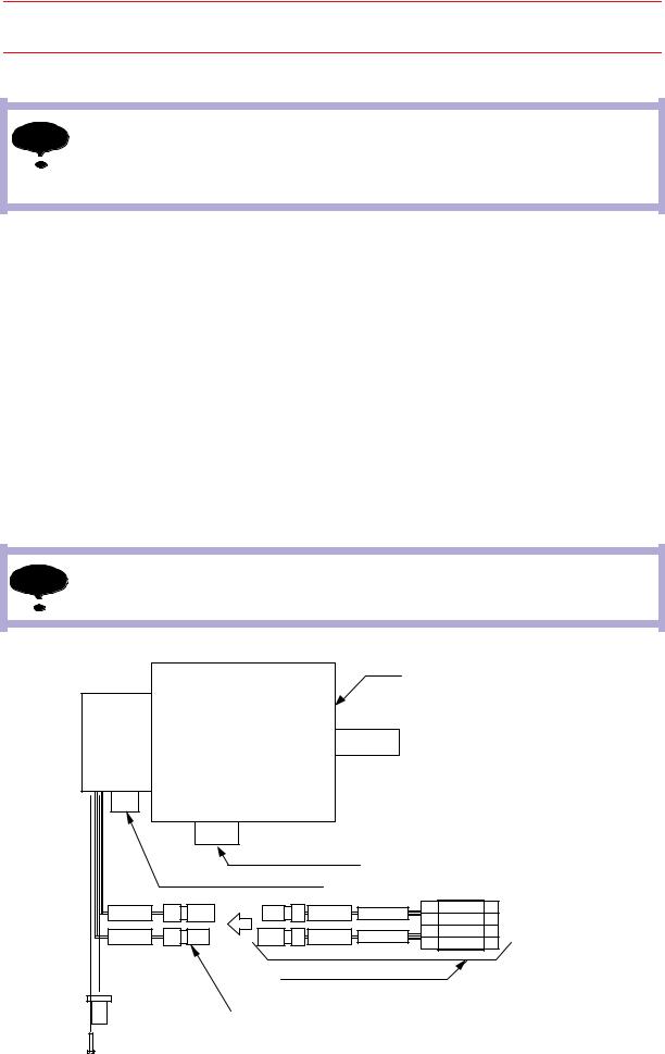
For the battery pack connection, refer to " Fig. 29 Battery Pack Connections ".
Battery Pack Connection for Motor
The connectors: crimped contact-pins for the battery backup are installed at the end point of the motor. As "BAT" and "OBT" are marked on the backup connectors and battery packs, connect the battery packs and connectors with the same marks respectively.
Connect the battery pack in accordance with the following procedure.
1.Remove the cap attached to the battery backup connector of the motor.
2.Connect the battery pack (HW9470932-A) with the connectors for battery backup (marked as BAT and OBT), which are located at the end of the motor encoder cable. (With the connectors and battery packs connected, remove the encoder connector and carry out maintenance checks.)
3.After the maintenance checks, ensure that all the connectors are properly connected. Remove the battery pack, then reinstall the cap for the battery backup connector of the motor.
NOTE Do not remove the battery pack in the connector base.
Motor
|
|
Motor power connector |
|
|
Connector for motor encoder |
||
0BT |
b |
a |
0BT* |
BAT |
a |
b |
BAT* |
|
|
Battery pack: HW9470932-A |
|
Connector for battery backup
a: Crimped contact-pin (pin)
b: Crimped contact-pin (socket)
Fig. 29 Battery Pack Connections
9-22
HW0482904 56/73