

SGH_i900_service_manual-spaces_ru
.pdfExploded View and Parts List
 17
17 
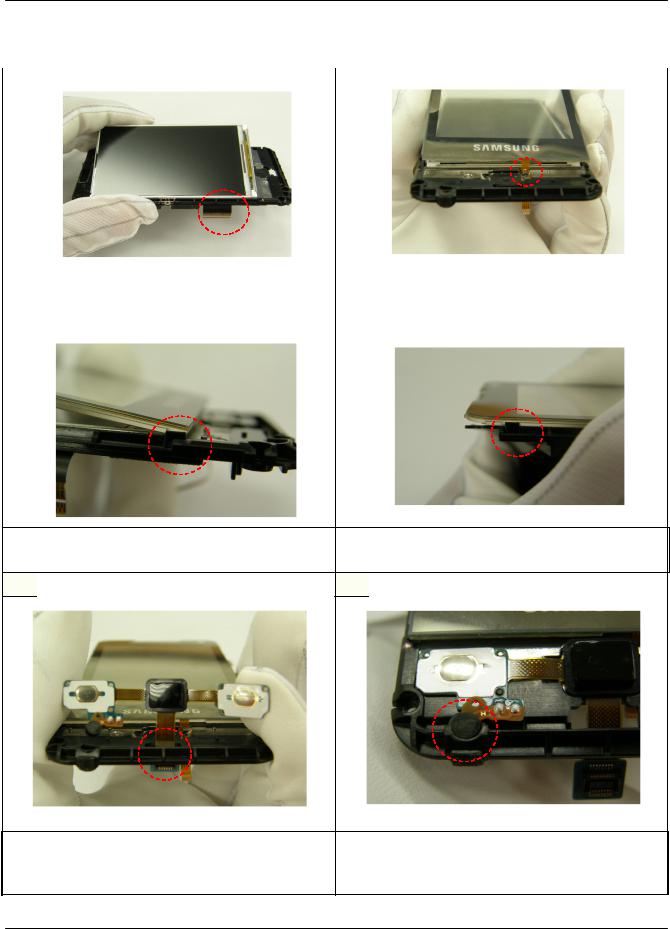
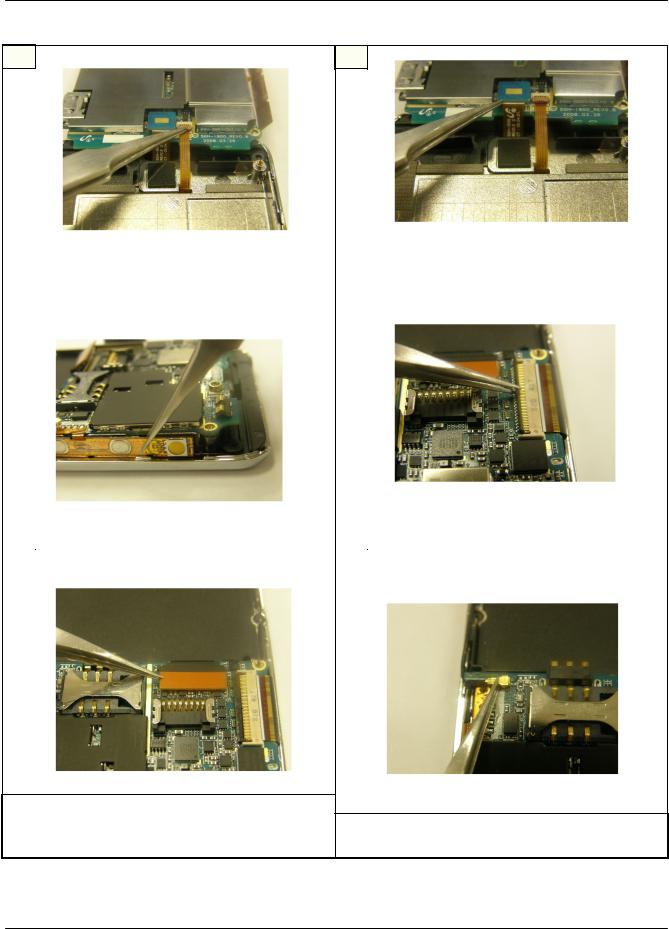
use this point to separate OJ Key easily
Separate OJ(Optical Joystic) KEY FPCB..
- Separate FPCB from FRONT Ass`y using guide hole.
19 
 18
18 
Separate TSP Module.
- Separate TSP Module from PBA with care.
use this point to separate LCD easily
Separate LCD from TSP.
-Separate LCD from TSP with great care not to damage TSP.
7-5
SAMSUNG Proprietary-Contents may change without notice
This Document can not be used without Samsung's authorization
Exploded View and Parts List
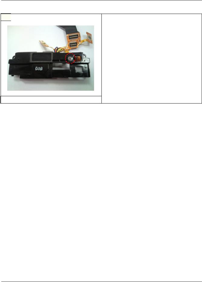
7-2. SPK Disassembling
1 |
2 |
|
|
|
|
|
|
|
|
|
|
|
|
|
|
|
|
|
|
|
|
|
|
|
|
|
|
|
|
|
|
|
|
|
|
|
|
|
|
|
|
|
|
|
|
|
|
|
|
|
|
|
|
|
|
|
|
|
|
|
|
|
|
|
|
|
|
|
|
|
|
|
|
|
|
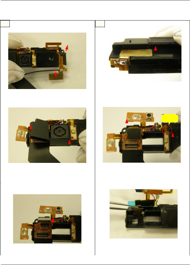
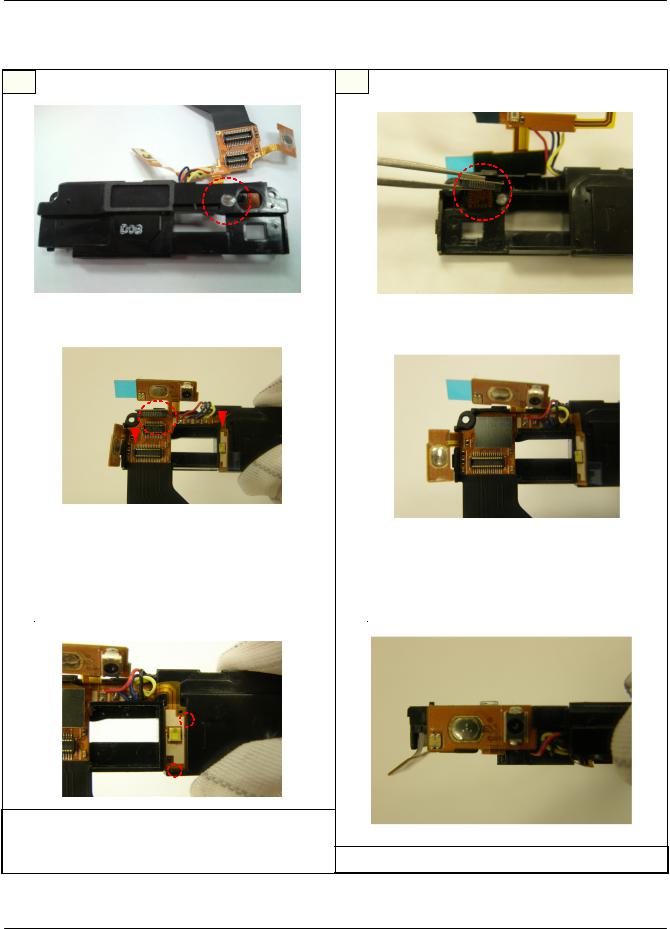
Detach GPS FPCB & GPS wire - 2. |
||||||||||
|
|
|
|
|
|
- Detach metal part of FPCB & GPS wire from |
||||||||||
Detach GPS FPCB - 1. |
|
|
|
|||||||||||||
|
|
|
SPK Bracket. |
|||||||||||||
|
|
|
|
|
|
|||||||||||
3 |
|
|
|
|
|
4 |
|
|
|
|
|
|
|
|
|
|
|
|
|
|
|
|
|
|
|
|
|
|
|
|
|
|
|
|
|
|
|
|
|
|
|
|
|
Caution! |
|
|||||
|
|
|
|
|
|
|
|
|
|
|
||||||
|
|
|
|
|
|
|
|
|
|
|
|
|
|
|
|
|
|
|
|
|
|
|
|
|
|
|
|
|
|
|
|
||
|
|
|
|
|
|
|
|
|
|
|
|
|
|
|
||
|
|
|
|
|
|
|
|
|
|
|
|
|
|
|
||
|
|
|
|
|
|
|
|
|
|
|
|
|
|
|
||
|
|
|
|
|
|
|
|
|
|
|
|
|
|
|
||
|
|
|
|
|
|
|
|
|
|
|
|
|
|
|
||
|
|
|
|
|
|
|
|
|
|
|
|
|
||||
|
|
|
|
|
|
|
|
|
|
|
|
|
||||
|
|
|
|
|
|
|
|
|
|
|
|
|
|
|
|
|
|
|
|
|
|
|
|
|
|
|
|
|
|
|
|
|
|
|
|
|
|
|
|
|
|
|
|
|
|
|
||||
|
|
|
|
|
|
|
|
|
|
|
|
|
||||
|
|
|
|
|||||||||||||
|
|
|
|
|||||||||||||
|
|
|
|
|
|
|
|
|
|
|
|
|
|
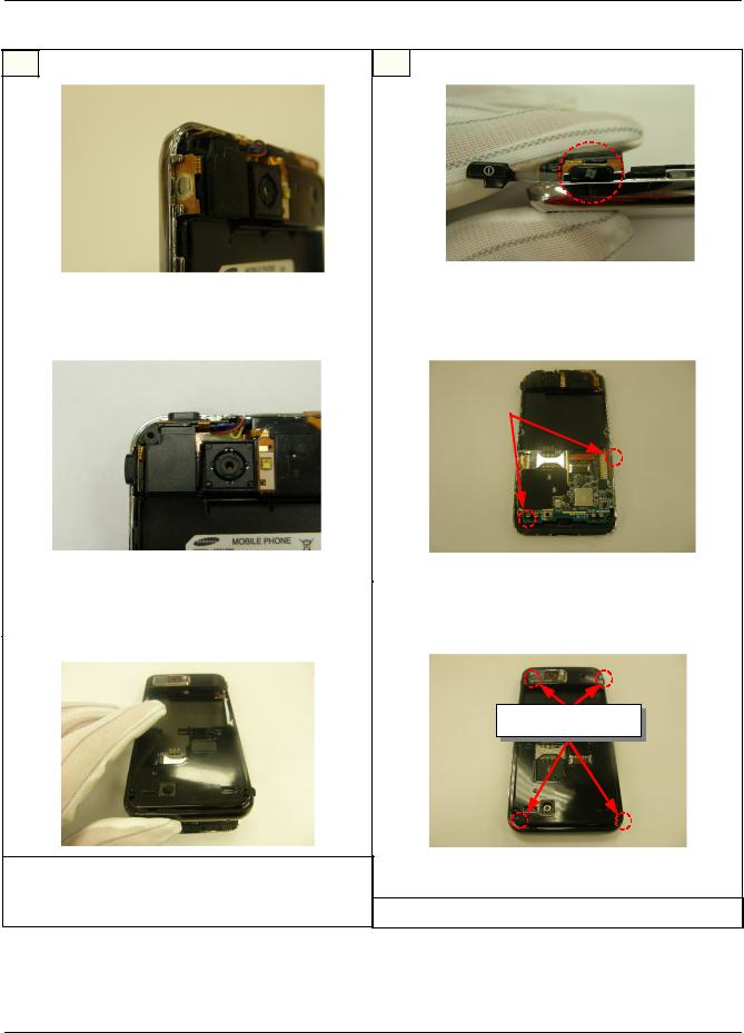
Disassemble 5M CAM CONNECTOR. |
Detach Flash FPCB & Power Key. |
|||||
- Separate 5M CAM Connector First. Then Pull 5M |
- Caution : Detach Flash FPCB from Bracket with |
|||||
CAM out of Bracket. |
great care not to tear FPCB. |
|||||
|
|
|
|
|
|
|
5 |
|
|
|
6 |
|
|
|
|
|
|
|
|
|
|
|
|
|
|
|
|
|
Separate Main FPCB from SPK Bracket & Remove |
Disassemble CIF CAM CONNECTOR. |
CIF CAM. |
|
|
7-6
SAMSUNG Proprietary-Contents may change without notice
This Document can not be used without Samsung's authorization
Exploded View and Parts List
 7
7 
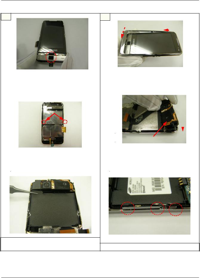
Disassemble Window Deco.
7-7
SAMSUNG Proprietary-Contents may change without notice
This Document can not be used without Samsung's authorization
Exploded View and Parts List
7-3. Assembling |
|
|
|
|
|||
1 |
|
|
|
|
|
2 |
|
|
|
|
Attach the |
left side of LCD first. |
|
|
|
|
|
|
|
|
|
|
|
|
|
|
|
|
|
|
|
Attach LCD to the Main Shield Can. |
Insert TSP FPCB into the hole. |
||
- Insert LCD connector into the hole and then |
- Insert TSP FPCB into the smaller hole of the |
||
attach LCD to the main shield can. |
Two. |
||
|
|
|
|
3 |
|
4 |
|
Attach TSP on the LCP - 1.
- Attach TSP referring to the Guide.
 5
5 
Attach TSP on the LCP - 2.
- Attach TSP referring to the Guide.
 6
6 
Insert OJ Key FPCB into the hole.
- Insert OJ(Optical Joystic) Key FPCB into the larger hole of the Two.
Attach OJ Key on the Main Shield Can.
-Attach OJ Key referring to the Guide.
-MIC should fit in the hole.
7-8
SAMSUNG Proprietary-Contents may change without notice
This Document can not be used without Samsung's authorization
Exploded View and Parts List
7 |
8 |
|
|
|
|
|
|
|
|
|
|
|
Assemble Key Pad with OJ Key. |
Assemble FRONT with FRONT Ass`y. |
|||||||||
- Optical Joystic should fit in the hole of |
- Assemble FRONT with FRONT Ass`y following |
|||||||||
Key Pad. |
indicated direction. |
|||||||||
|
|
|
|
|
|
|
|
|
|
|
9 |
|
|
|
|
10 |
|
|
|
|
|
|
|
|
|
|
|
|
|
|
|
|
|
|
|
SCREW 2 POINTS |
|
|
|
|
|
|
|
|
|
|
|
|
|
|
|
|
|
|
|
|
|
|
|
|
|
|
|
|
|
|
|
|
|
|
|
|
|
|
|
|
|
|
|
|
|
|
|
|
|
|
|
|
|
|
|
|
|
|
|
|
|
|
|
|
|
|
Bracket Assembly : refer to 5/6 page |
|
|
|
|
|
|
|
|
|
|
|
|
|
|
|
|
|
|
|
|
Attach SPK Bracket. |
|||||
|
|
-Attach SPK Bracket on the FRONT Ass`y referring |
|||||
Screw 2 FRONT Points. |
to the Guide. |
||||||
|
|
|
|
|
|
|
|
11 |
|
12 |
|
|
|
|
|
Attach Bracket Sheet.
- Attach Bracket sheet considering guide line.
Put the GPS wire into FRONT Ass`y Guide.
7-9
SAMSUNG Proprietary-Contents may change without notice
This Document can not be used without Samsung's authorization
Exploded View and Parts List
13 |
14 |
Assemble TSP FPCB CONNECTOR. |
Assemble OJ Key FPCB CONNECTOR. |
||
- Assemble TSP FPCB Connector with PBA |
- Assemble OJ Key FPCB Connector with PBA |
||
Connector. |
Connector. |
||
|
|
|
|
15 |
|
16 |
|
|
|
Assemble LCD FPCB CONNECTOR. |
|
|
|
- Assemble LCD FPCB Connector with PBA |
|
Attach Volume Key FPCB to FRONT Ass`y. |
Connector. |
||
|
|
|
|
17 |
|
18 |
|
Assemble Main FPCB CONNECTOR.
- Assemble Main FPCB Connector with PBA Connector.
Assemble GPS CONNECTOR.
- Assemble GPS Connector with PBA Connector.
7-10
SAMSUNG Proprietary-Contents may change without notice
This Document can not be used without Samsung's authorization
Exploded View and Parts List
19 |
20 |
Put the Fuction Key FPCB into FRONT Ass`y |
Assemble Window Function key - 1. |
|||||
Guide. |
- The Rounded part is headed to the TOP. |
|||||
|
|
|
|
|
|
|
21 |
|
22 |
|
|
|
|
|
|
|
|
|
|
|
|
|
|
|
|
SCREW 2 POINTS |
|
|
|
|
|
|
|
|
|
|
|
|
|
|
|
Assemble Window Function key - 2. |
|
Screw 2 PBA Points. |
||
|
|
|
|
|
23 |
|
24 |
|
|
SCREW 4 POINTS
Assemble the REAR with FRONT Ass`y. |
|
- Assemble REAR with FRONT Ass`y considering |
|
GPS wire, Window Fuction key and IF cover. |
Screw 4 REAR Points. |
7-11
SAMSUNG Proprietary-Contents may change without notice
This Document can not be used without Samsung's authorization
Exploded View and Parts List
7-4. SPK Assembling |
2 |
1 |
Assemble Window Deco. |
Assemble CIF CAM. |
||||
|
|
|
|
|
|
3 |
|
|
|
4 |
|
|
|
|
|
|
|
|
|
|
|
|
|
|
|
|
|
|
|
|
|
|
|
|
|
|
|
|
|
|
|
|
|
|
|
|
|
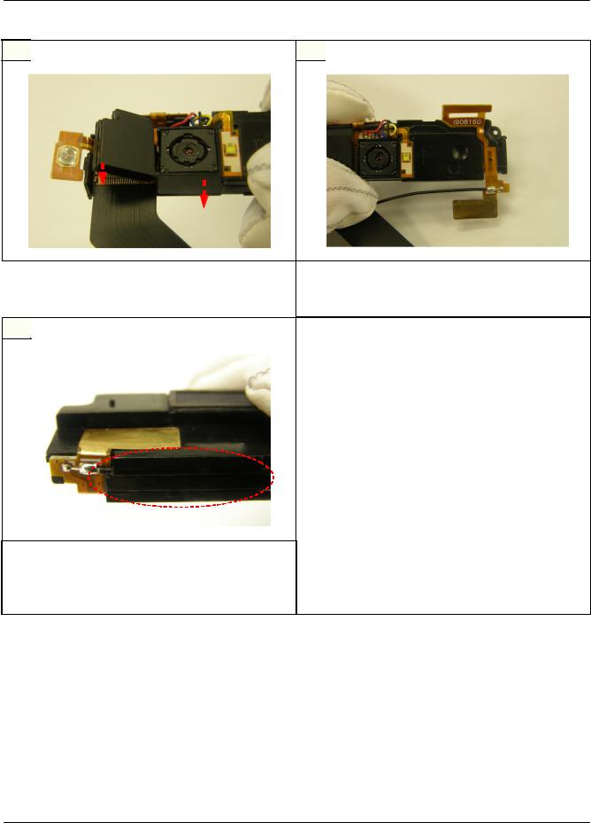
Make Main FPCB fit in SPK Bracket. |
|
|
|
- Attach Main FPCB between CIF CAM and its |
Assemble CIF CAM CONNECTOR. |
||
Connector. Main FPCB should be stuck on SPK |
- Assemble CIF CAM Connector with PBA |
||
Bracaket inside. |
Connector. |
||
|
|
|
|
5 |
|
6 |
|
Attach Flash FPCB. |
|
- Attach Flash FPCB to SPK Bracket referring to |
|
the Guide. |
Attach Power Key. |
7-12
SAMSUNG Proprietary-Contents may change without notice
This Document can not be used without Samsung's authorization
Exploded View and Parts List
 7
7 

Assemble 5M CAM CONNECTOR.
- Assemble 5M CAM Connector with FPCB Connector following indicated direction.
9 
 8
8 
Attach GPS FPCB - 1.
- Attach GPS FPCB to SPK Bracket referring to the Guide.
Attach GPS FPCB & wire - 2.
- Attach metal part of FPCB to SPK Bracket behind. Then Put GPS Wire into SPK Bracket Guide.
7-13
SAMSUNG Proprietary-Contents may change without notice
This Document can not be used without Samsung's authorization
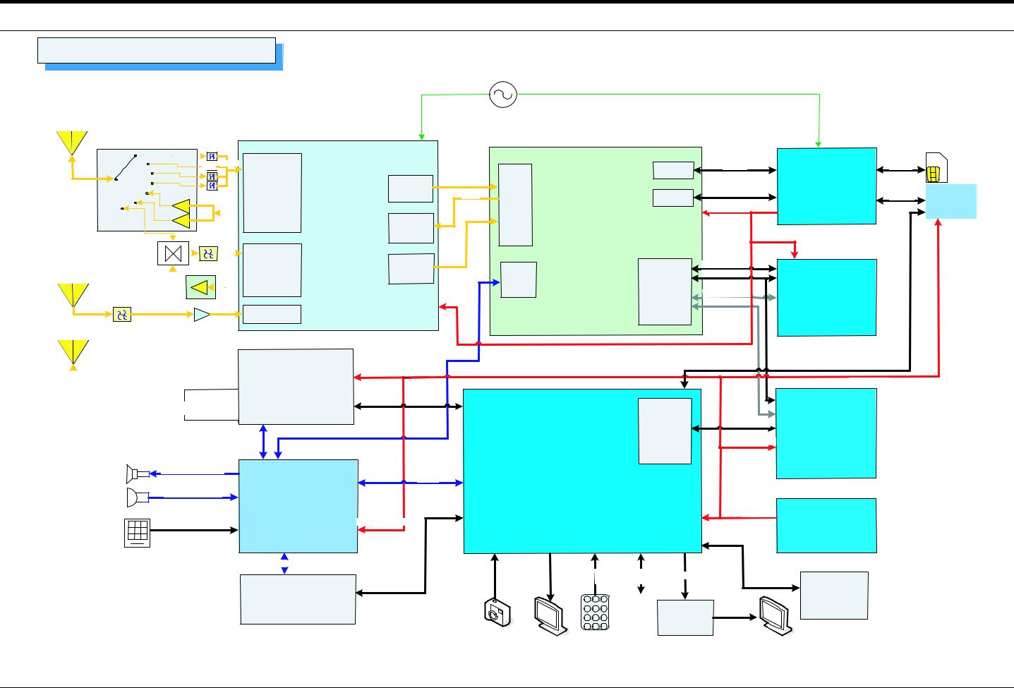
8. Block Diagrams
SGH-i900 Block Diagram
Main Ant.
GPS Ant.
BT /w LAN Ant.
TCXO 19.2MHz
2. |
5G PAM |
|
|
/ |
Swi t ch |
|
|
|
|
|
|
|
|
|
|
SKY77519


 2.5G Rx
|
|
|
|
|
|
2.5G |
|
|
|
|
|
|
|
|
|
|
2.5G Tx |
RF Block |
||
|
|
|
|
|||
|
|
|
|
3G Rx |
|
|
|
|
|
|
|
|
UMTS |
|
|
|
|
3G Tx |
RF Block |
|
|
|
|
|
|
||
|
|
|
GPS Rx |
AGPS |
||
|
|
|
||||
|
|
|
|
|
|
|
|
|
|
|
|
|
|
RTR 6285
Rx IQ |
Rx IQ |
RF |
|
Tx IQ |
|||
|
|||
|
|
I/F |
|
|
GPS IQ |
Block |
|
|
|
||
Tx IQ |
|
|
GPS |
|
Audio |
IQ |
|
|
|
|
I/F |
|
Power |
|
|
|
|
|
_RF |
|
MSM6281
SIM I/F |
SIM I/O |
SIM I/F |
|
|
|
|
|
||
|
USB I/O |
PM6658 |
|
|
USB I/F |
USB I/F |
USB3319 |
||
|
||||
|
|
|||
|
Power_MSM |
|
||
|
|
|
|
|
Power_Flash |
|
|
MSM_D1(0-31) |
|
|
Memory |
MSM_D2(0-15) |
|
|
|
Main Memory |
||
I/F |
MSM_A1(0-12) |
||
K5D1258DCA |
|||
Block |
MSM_A2(1-13) |
||
-A090 |
|||
|
|||
|
|
 BT/wLAN LBEE1USJYC
  26MHz
26MHz
Audio I/F
PCM Audio
Power_BT/wLAN
BT/wLAN
Data
Memory
I/F
Block
|
USB Data |
|
Power_USB |
DF_IO(0-15) |
DPRAM |
|
|
Power_DPRAM CDYDMX128A16-1 |
|
Speaker/EP Output |
Sound |
||
|
|
Data |
|
|
MIC/EarMIC Input |
WM9713 |
|
C |
|
||
Touch I/F |
Power_CODEC |
||
|
|||
|
|
||
88AP312-A2-BGW1C624-TN02
Power_AP
RADIO R/L |
|
|
|
|
|
|
|
|
|
I2C |
CAM |
LCD |
Key |
Ext. Mem. |
TV OUT |
|
|
|
|||||
|
|
|
data |
data |
input |
I/F |
|
|
|
|
|
FM RADIO |
1 |
2 |
3 |
|
|
SI4703-B16-GM |
4 |
5 |
6 |
TV |
TV OUT |
|
|
||||
|
7 |
8 |
9 |
ISE2200 |
|
|
* |
0 |
# |
|
|
|
|
|
8-1
SAMSUNG Proprietary-Contents may change without notice
AP_PMIC MAX8660ETL
Internal Memory (8GB/16GB)
This Document can not be used without Samsung's authorization