

laser_measurement_instruments_catalog
.pdf3.5 Near Field Profilers
3.5.1 Camera Based Near-Field Profiler
ֺAllows measurement of beams normally too small for camera profiler
ֺExpands beam to reduce power/energy density
ֺProvides near-field profile of fibers, LD junctions, and other small sources
ֺCan be used to measure tightly focused beam with camera and attenuation
ֺNominal 10X, 20X, 40X, 60X Beam expansion available
ֺEasily calibrated to provide absolute measurement values
ֺBuilt-in continuously variable attenuation
ֺC-mount for attachment to any camera profiler
ֺCamera and BeamGage software purchased separately
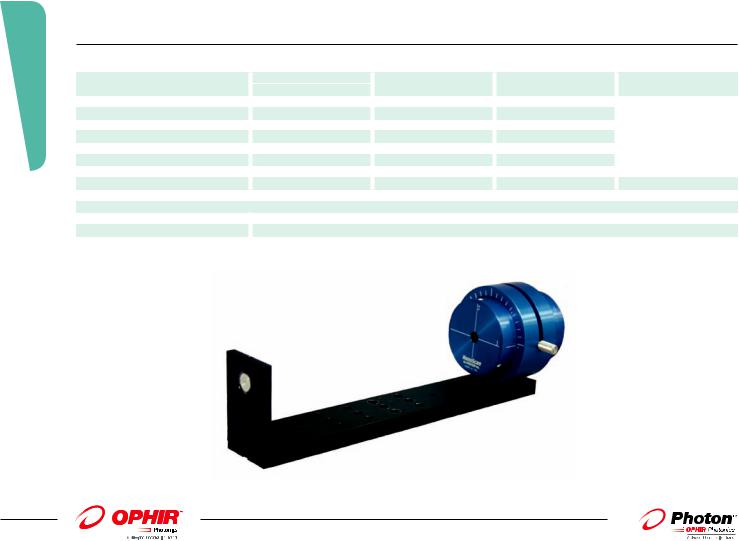
Near field profiling can also be used with camera profilers to analyze small beams, and involves a microscope objective lens to image the beam onto a camera detector array. This technique expands the measurement range of the camera to include smaller beams, which could not be ordinarily measured due to the pixel size of the detector array. Near field profiling is performed in fiber and waveguide analysis, lens characterization, and other applications where beams 50 microns or smaller are analyzed. While there are more accurate techniques to measure these beam sizes, the camera provides two-dimensional information that cannot always be obtained through knife-edge or scanning slit methods. This camera accessory includes base plate for mounting camera and Microscope Objective, ATP-K variable attenuator, 50mm C-Mount and an 8mm and 5mm spacer. User selectable magnification lenses, camera and BeamGage must be purchased separately.
The near field of the test beam or sample is imaged with the microscope objective lens and relayed to the camera. The bracket mounting fixture holds both the lens and camera, which itself can be mounting on a positioner or optical rail. This complete system provides everything necessary to perform near-field measurements right out of the box.
|
|
|
|
|
Camera NFP with ATP-K |
|
|
|||
|
|
|
|
|
Variable Attenuator |
|
|
|||
C-mount NFP Adapter Assembly |
|
|
||||||||
|
ATP-K Variable ND Filter |
|
|
|||||||
Fixed ND Filter |
Light Baffle |
|
Locking Ring 8mm C-mnt extender |
|
|
|||||
|
|
|
|
|
|
|
|
5mm C-mnt |
|
|
|
|
|
|
|
|
|
|
|
|
|
|
|
|
|
|
|
|
|
|
|
|
|
|
|
|
|
|
|
|
extender |
|
|
Microscope Objective |
|
|
|
|
Camera sold separately |
|
|
|||
sold separately |
C-NFP Adapter |
|
|
|
||||||
|
|
|
|
|
|
|
||||
Ordering Information |
|
|
|
|
|
|
|
|
|
|
|
|
|
|
|
|
|
|
|
|
|
Item |
|
|
|
Description |
|
P/N |
||||
C-NFP Assy |
|
|
|
Includes base plate for mounting camera and Microscope Objective, ATP-K variable attenuator, |
|
SP90291 |
||||
|
|
|
|
50mm C-Mount and an 8mm and 5mm spacer. |
|
|
||||
60X |
|
|
|
60X, Microscope objective |
|
SP90292 |
||||
40X |
|
|
|
40X, Microscope objective |
|
SP90293 |
||||
20X |
|
|
|
20X, Microscope objective |
|
SP90294 |
||||
10x |
|
|
|
10X, Microscope objective |
|
SP90295 |
||||
3.5.1 Beam Analysis
199
For latest updates please visit our website: www.ophiropt.com/photonics |
|
01.04.2014 |
3.5.2 Beam Analysis
200
3.5.2 Slit-Based NanoScan Near-Field Profiler
Measuring the near field of sources such as laser diodes, VCSELs, optical fiber, and/or waveguides can be a difficult task. Accurate measurement of such small sources to the micron level requires high precision in the optical and mechanical design. To simplify this task and to fill this requirement, Photon offers several models of Near-Field Profilers (NFPs) covering a wide range of wavelengths and power levels. Another important application of these instruments is to extend the focused laser spot size measurement range of the NanoScan profiler. By expanding the size of a focused spot it is possible to reduce the power density and make possible the measurement of beams that are too powerful to be measured without attenuation, as well as those that are too small to be accurately measured with the standard scanhead. The NanoScan NFPs are easy-to-use turnkey systems that can be used either as a stand-alone instrument or integrated into manufacturing inspection systems. For NanoScan users who want to extend the measurement capability of their present systems, the optical and mechanical components are also available as accessories.
The NFP-980 with 60:1 magnification and 1µm resolution, specifically designed for measurement of 980nm pump lasers, is also ideal for other applications in the wavelength range between 700nm–1100 nm. The NFP-1550, with 40:1 magnification and 2.6µm resolution, is designed for use in characterizing sources in the 1300-1600nm telecommunications wavelength band. Both models come with a NanoScan GE/9/5 scanhead and the magnifying objective lens, which can be rigidly mounted to an optional precision XYZ translation stage, which in turn is mounted to an optical rail. They also include the NanoScan Control and Data Acquisition Card and NanoScan Acquisition and Analysis Software. The system has all the standard Windows file saving, printing, communication and ActiveX capability.
For visible wavelengths, the NFP-VIS is equipped with the NanoScan SI/9/5 scanhead and the 60:1 microscope objective, AR coated for the 400–700nm wavelength range. UV Wavelengths below 360nm can also be accommodated with an optional UV corrected microscope objective. For higher power and longer wavelength beams the NFP-Pyro is available. These systems can measure spot sizes from 5μm at any wavelength from 190nm to 20μm. This instrument configuration naturally reduces the power density incident on the instrument by one over the square of the magnification. The system can be supplied with a lens for the user-specified wavelength of use.
For viewing VCSEL junctions, single-mode fibers and large long wavelength LD junctions there is an optional 100:1 objective lens option, producing diffraction limited performance from 400–700nm with a working distance of approximately 0.25-0.35mm and Numerical Aperture is 0.90. From 700–1600nm, this lens produces near diffraction-limited performance.
NanoScan Near-Field Profiler Systems
Parameter |
NFP-VIS |
NFP-980 |
NFP-1550 |
NFP-Pyro |
|
|
|
|
|
|
|
Tester Wavelength Range |
400-700nm |
700-1100nm |
1300-1700nm |
190->20μm |
|
|
<360nm optional |
|
|
|
|
Lens Spread Function |
0.49μm |
1.1μm |
2.6μm |
|
|
Maximum Source |
140μm |
140μm |
200μm |
Wavelength and |
|
Objective Focal Length |
3mm |
3mm |
5.1mm |
|
|
application dependent for |
|
||||
Objective Rear Focal Distance |
160mm |
160mm |
207mm |
|
|
these parameters |
|
||||
Objective Numerical Aperture |
0.85 |
0.85 |
0.48 |
|
|
|
|
||||
Objective Magnification |
60:01:00 |
60:01:00 |
40:01:00 |
|
|
NanoScan Model |
NSSI/9/5 |
NSGE/9/5 |
NSGE/9/5 |
NSPyro/9/5 |
|
Aperture Size |
9mm |
9mm |
9mm |
9mm |
|
Slit Width |
5μm |
5μm |
5μm |
5μm |
|
3 Axis Stage Travel |
|
|
|
|
|
X (across rail) |
13mm micrometer adjust |
|
|
|
|
Y (normal to rail) |
6.5mm fine pitch actuator |
|
|
|
|
Z (along rail) |
13mm micrometer adjust |
|
|
|
|
01.04.2014 |
|
For latest updates please visit our website: www.ophiropt.com/photonics |
|

Ordering Information
Item |
Description |
P/N |
|
|
|
|
|
|
|
Model USB NFP-1550(NS) |
Model NFP-1550 NanoScan system with Germanium Detector 9mm Aperture 5µm Slits. High- |
PH00229 |
|
|
|
resolution 63.5mm diameter head with rotation mount. Use from 700nm to 1.8microns |
|
|
|
Model USB NFP-980(NS) |
Model NFP-980 NanoScan Germanium Detector 9mm Aperture 5.0micron Slits. High-resolution |
PH00230 |
|
|
|
63.5mm diameter head with rotation mount. Microscope Objective Lens Mount with 60:1 optics for |
|
|
|
|
700-1100nm |
|
|
|
Model USB NFP-VIS(NS) |
Model NFP-VIS NanoScan Silicon Detector 9mm aperture 5µm slits. High-resolution 63.5mm |
PH00231 |
|
|
|
diameter head with rotation mount. Microscope Objective Lens Mount Bracket with 60:1 optics for |
|
|
|
|
400-700nm |
|
|
|
Model USB NFP-Pyro |
NFP-NS-Pyro NanoScan pyroelectric detector with 9mm entrance 5µm slits. Use for wavelengths |
PH00232 |
|
|
|
from 190mm to 20 microns (specify wavelengths of use when ordering). Lens Mount bracket with |
|
|
|
|
well-corrected aspheric high-energy 60:1 lens with a 0.68 NA. Available in wavelengths 400nm- |
|
|
|
|
1100nm |
|
|
|
3.5.2 Beam Analysis
201
For latest updates please visit our website: www.ophiropt.com/photonics |
|
01.04.2014 |

3.6 Beam Analysis
202
3.6 What is M2 ?
M2, or Beam Propagation Ratio, is a value that indicates how close a laser is to being a single mode TEM00 beam, which in turn determines how small a beam waist can be focused. For the perfect Gaussian TEM00 condition the M2 equals 1.
For a laser beam propagating through space, the equation for the divergence, θ, of an unfocused beam is given by:
θ0 = M24λ/πD0
For a pure Gaussian TEM00 beam M2 equals 1, and thus has no impact on the calculation. The calculation of the minimal beam spot is then:
d0 = 4λ/πθ
Again with M2 equal to 1, the focused spot is diffraction limited.
Characteristics of a laser beam as it passes through a focusing lens.
For real beams, M2 will be greater than 1, and thus the minimum beam waist will be larger by the M2 factor.
How is M2 measured?
M2 cannot be determined from a single beam profile measurement. The ISO/DIS 11146 requires that M2 be calculated from a series of measurements as shown in the figure above. M2 is measured on real beams by focusing the beam with a fixed position lens of known focal length, and then measuring the characteristics of the artificially created beam waist and divergence.
To provide an accurate calculation of M2, it is essential to make at least 5 measurements in the focused beam waist region, and at least 5 measurements in the far field, two Rayleigh ranges away from the waist area. The multiple measurements ensure that the minimum beam width is found. In addition, the multiple measurements enable a “curve fit” that improves the accuracy of the calculation by
minimizing measurement error at any single point. An accurate calculation of M2 is made by using the data from the multiple beam width measurements at known distances from a lens, coupled with the known characteristics of the focusing lens.
M² Measurement Solutions
Ophir-Spiricon and Photon have a number of solutions for the measurement of M² ranging from simple manual processes to fully automated dedicated instruments, depending on the frequency of the need to measure M² of lasers and laser systems. We have a system that will meet most needs, whether for research and development of new laser systems, manufacturing quality assurance, or maintenance and service of existing systems.
01.04.2014 |
|
For latest updates please visit our website: www.ophiropt.com/photonics |
|

3.6.1 
Camera Based Beam Propagation Analyzer: M2
M2-200s
ֺAutomatically measure your beam quality in under 2 minutes
ֺTune your laser for best operation
ֺISO compliant
ֺSpecifically developed for continuous usage
ֺUnequaled accuracy using patented UltracalTM Calibration
ֺAutomatic attenuation adjustment
ֺPulsed and CW for most beam diameters and powers
ֺCompact and portable
Not all commercial M2 measuring instruments conform to the ISO 11146 method of employing a fixed position lens and moving
detector. Instead, some manufacturers use a fixed position detector and a moving lens. If the laser beam is diverging or converging within the travel range of a moving lens, the reported M2 value and other results can be significantly compromised. Spiricon's
M2-200s Beam Propagation Analyzer is fully ISO 11146 compliant.
Automatic M2 - at Production Speeds
The M2-200s optical train uses a fixed position lens and camera. The mirrors that direct the focused beam into the camera are moved to precise locations, translating the beam through both the waist region and the far field regions. All these measurements and translations, as well as incremental beam attenuation, are automatically controlled by the M2-200s software. Software improvements in the M2-200s, including more efficient algorithm execution, has decreased the measurement reporting time by 2-3 times, making it possible to report M2 in under two minutes.
Steering Mirrors
Beam Attenuater
1st
Laser Source
“A” “B”
2nd 
 Camera
Alignment Tool
 m2-200s Optical Train
3.6.1 Beam Analysis
203
For latest updates please visit our website: www.ophiropt.com/photonics |
|
01.04.2014 |

3.6.1 Beam Analysis
Manual M2
Manual mode is available for beams that are too large or too small or at wavelengths outside the standard optical train.
Mirror 2 |
Lens |
Filters |
Camera
Laser Source
Mirror 1
Accuracy by Design
Spiricon products are known for accuracy. Using our patented UltracalTM calibration method and auto aperturing to exclude noise beyond the wings of the laser beam, assures the user of the most accurate measurements in the industry.
Designed by Our Customers
Spiricon has redesigned the M2-200, the world's top selling beam propagation system to include customer input, increased attention to durability, and operational robustness for continuous use applications - three shifts a day, seven days a week. Novice and seasoned users will appreciate these new features along with the time-tested excellence that the Spiricon M2-200 measurement system has provided over the years.
Main Screen Functions
This window displays quantitative measurements of the laser parameters. These include the X and Y beam widths, M2 or K, the divergence angles, the Rayleigh range, and other parameters shown.
This window presents measurements of beam width vs. position for a given run. After measuring a few points, the software
extrapolates a curve fit. The Xs and Ys represent individual measurement points. The solid
lines present the best fit hyperbola of the beam propagation equation to the measured points. The M2 and other laser parameters are computed from the best fit hyperbola since it provides a smoothing of the data points.
The 2D or 3D beam profile of the currently measured point in the beam propagation curve. This image enables visual intuitive verification of the beam profile behavior through focus. After each run the user can click any individual measured point and observe the beam profile. Outlying or anomalous points can be automatically or manually excluded from the curve fit calculations for more accurate results.
204
01.04.2014 |
|
For latest updates please visit our website: www.ophiropt.com/photonics |
|

3.6.1.1 Specifications for the M2-200s
General |
|
Accuracy |
±5% typical, ±12% waist location and Rayleigh length typical (Note: Accuracy can be degraded by a variety of situations) |
Measurement Cycle Time |
2-3 minutes typical, depending on setup conditions and operating mode |
Camera Attachment |
Std C-mount, 90° camera on axis rotation |
Translation System |
Step motor-driven lead screw |
Translation Pitch |
4 mm/rev optical pitch |
Step Angle |
1.8° (200 steps/rev) |
Sample Range |
M2 - 200 s 190 - 600 mm, typical |
Camera Specifications (for GRAS20 camera) |
|
Imager |
1/1.8” CCD, 1600 x 1200 pixels |
Dynamic Range |
12 bit A to D |
Frame Rates |
7.5 FPS (at full resolution) |
Pixel size |
4.4µm x 4.4µm |
Gain |
0 to 25dB |
Shutter Control |
Programmable from 110µs to 70ms |
S/N Ratio |
59dB at min gain |
Trigger Input |
Edge sensitive 3.3 / 5Vdc LVTTL / TTL (positive or negative, user programmable) |
|
Minimum pulse width 10us |
Trigger Out |
External Trigger cable provided |
Voltage Requirement |
3.3Vdc LVTTL, Programmable |
Power Consumption |
Powered over Firewire Cable |
|
<3.5watts |
Dimensions |
44mm (1.74") wide, 29mm (1.14") tall and 66mm(2.6") deep |
Mass |
104g (3.7oz) |
Environmental |
|
Storage Temperature |
-30°C to 65°C |
Storage Humidity |
95% maximum (non-condensing) |
Operating Temperature |
10°C to 40°C |
Operating Humidity |
95% maximum (non-condensing) |
Power Requirements* |
|
Line Voltage |
95V AC to 250V AC |
Line Frequency |
47Hz to 63Hz |
Maximum Power |
4.5 Watts |
* For the Optical Train only. The PC computer supplies the power for the system components, such as the CCD camera. An external power supply is provided for Laptop computer use.
Physical |
M2-200s… 6.8 kg (without camera) |
|
Weight |
||
Measurements |
|
M2x, M2y, Kx, Ky, BPPx, BPPy |
Statistical results\ |
|
Width at waist Wx, Wy |
are available on |
|
Divergence angle qx, qy |
\all measurements |
|
Waist location Zx, Zy |
|
|
Rayleigh X, Y |
|
|
Astigmatism |
Asymmetry ratio
Wavelength Range
Different lenses are needed for different wavelength regions
The M2-200s model include 3 standard lenses with nominal 300mm focal lengths. See below
266 - 587nm (included)
400 - 750nm (included)
650 - 1125nm (included)
1000 - 1300nm (optional)
Attenuation Range Nominally from ND 0 to ND 4.8. Actual values vary with wavelength
Beam Size |
0.5mm - 10mm |
M2-200s |
Damage Limits 1 |
Varies with wavelength, waist size and location, and M2 |
|
|
|
|
Camera |
0.15 µW/cm2 CW mode for a 10 mm input beam diameter |
|
|
1.0 µJ/cm2 pulse mode for a 10 mm input beam diameter |
|
|
Both of the above for an M2 =1 @ 1064nm |
|
1 CCD cameras can be damaged by power in excess of 100 mW/cm2 or energy in excess of 100 mJ/cm2. The M2-200s employs a focusing optic. While it may be that the laser input power or energy measures well below this damage threshold, it can easily exceed these levels when
focused onto the camera sensor. Use caution and error on the side of safety. CCD cameras can be costly to repair or replace.
Ordering Information
Item |
Description |
P/N |
|
|
|
M2-200s Beam Propagation Analyzer |
|
|
M2-200s-FW |
M2-200 software, software license, GRAS 20 Firewire camera, short optical train, automatic and manual |
SP90144 |
|
operation, recommended for 266nm - 1064nm wavelengths |
|
M2-200s-FW-A |
M2 |
SP90145 |
|
-200 software, software license, short optical train, automatic and manual operation, recommended for 266nm - |
|
|
1064nm wavelengths (GRAS 20 camera not included) |
|
M2-200sM-FW |
Manual mode M2-200 software, software license, GRAS 20 Firewire camera, manual operation with a GRAS 20 |
SP90146 |
|
Firewire camera (optical train not included) |
|
M2-200sM-FW-A |
Manual mode M2-200 software, software license, manual operation with a Firewire camera (GRAS 20 Firewire |
SP90147 |
|
camera and optical train not included) |
|
1000-1300nm lens |
Lens assy telecom, 300mn fl |
11402-001 |
3.6.1.1 Beam Analysis
205
For latest updates please visit our website: www.ophiropt.com/photonics |
|
01.04.2014 |

3.6.1.2 Beam Analysis
3.6.1.2 Model 1780
Instantly measure M2
The ModeScan Model 1780 is a laser beam profiling instrument that measures the M² Beam Propagation Ratio and all associated ISO 11146 parameters instantaneously in real time at video rates to over 20Hz. The measurement technique, patented by Photon Inc., uses 10 reflective surfaces to form simultaneous images of the propagating beam at 10 locations on a Model 2512 CCD array camera. With all ten measurement positions acquired at once, the instrument is suitable for measurement of both CW and pulsed lasers down to single-shot rates. Beam diameters are obtained with NIST-traceable accuracy to better than 2% using the BeamPro. This translates to M² measurements with accuracy to ~5%. The FireWire system operates under Photon’s BeamPro in Microsoft Windows. The compactness of the system and the IEEE 1394a FireWire interface offers enhanced ease-of-use and portability. The ability to operate in any orientation allows for easy placement on any optical bench and saves valuable bench space.
The CCD is sensitive from ~250nm to 1100nm wavelengths. The standard |
|
configuration is supplied with a glass OD 2.8 C-mount neutral density filter for |
|
wavelengths >360nm, and an OD 3.0 Fused Silica Inconel neutral density filter for |
|
wavelengths <360nm. Because of the limited usefulness of exposure control with |
|
pulsed lasers, the Photon Inc. Model ATP is recommended for use with pulsed |
|
lasers with repetition rate <~10kHz and wavelength >360nm. For pulsed lasers |
|
with wavelength <360nm, a variable UV filter or a combination of UV filters will |
|
generally be required. |
ModeScan 1780 |
ModeScan Model 1780 System Specifications
Optical/Sensor/Detector |
|
Sensor |
Si CCD 1/2" Format |
Wavelength |
~360nm – ~1100nm (Standard with OD 2.8 filter) |
|
~250nm – ~1100nm with UV optics |
Pixel Array |
780 (H) × 580 (V) |
Pixel Size |
8.3µm × 8.3µm |
Array Dimension |
6.49mm × 4.83mm |
Scanning Mode |
Progressive |
CCD Cover Glass |
Removed |
Beam Splitters |
Fused Silica: <20/10 Scratch Dig, l/10 Flatness |
Test Lenses |
200mm fl Fused Silica/250 – 460nm AR coated standard |
UV: ~250 – 460nm |
200mm fl BK7/425 – 720nm AR coated standard |
Visible : 425 – 720nm |
200mm fl BK7/620 – 1080nm AR coated standard |
VIS – NIR; 620 – 1080n |
other fl's optional for all wavelengths |
|
|
Fixed Attenuator: Visible – NIR |
OD 2.8 Absorbing Glass >360nm |
UV |
OD 3.0 Fused Silica Inconel 250 – 450nm |
Computer/Electrical |
|
A / D Conversion |
12 Bit |
Maximum Frame Rate |
35.8fps (full frame @ full resolution) |
Exposure range |
20µs–27.64ms (Software selectable via 1394 bus) |
Gain |
0–12dB (Software selectable via 1394 bus) |
Trigger |
Internal or External (Software selectable) |
External Trigger Specifications |
5V ±1V @ 10mA ±5mA (Positive transition) |
Trigger Connector |
10 pin RJ-45 Jack |
Trigger Cable |
10 pin RJ-45 to BNC 1.8m |
Interface |
IEEE 1394a (FireWire) |
IEEE 1394 Cabl |
1.8m |
Supply Voltage |
+8V – +36V DC (+12V DC nominal), <1% ripple (supplied via IEEE 1394 cable); requires external powered hub with |
|
laptop PCs |
Supply Power |
3.5W max @ 12V DC (typical) |
Mechanical |
|
Filter/Lens Mount |
C-mount (1" – 32 tpi) |
Mounting |
Gimbal Mount on ½" post; 12mm Metric post optional |
Dimensions in mm |
62 H × 140 W × 210 L , + Gimbal Mount |
Weight |
~1.4kg |
Environmental |
|
Operating Temperature |
O° – +50°C (+32° – 112F) |
Humidity |
20% – 80%, relative, non-condensing |
Conformity |
CE; FCC; RoHS and WEEE |
206
01.04.2014 |
|
For latest updates please visit our website: www.ophiropt.com/photonics |
|

Arrangement of Measurement Windows: Video
Window Beam Propagation Mode; Beam Statistics
Window; Horizontal and Vertical Caustics Window.
Ordering Information
|
Item |
Description |
P/N |
|
|
|
|
|
|
|
|
|
|
|
ModeScan 1780 M2 System with |
|
|
|
|
|
|
Fire Wire BeamPro |
|
|
|
|
|
|
MS-1780 |
ModeScan Model 1780, dedicated M² measurement system, with 12-bit FireWire (IEEE 1394a) CCD |
PH00096 |
|
|
|
|
|
detector for single-shot, pulsed and CW lasers. System includes: ModeScan with gimbaled mount for |
|
|
|
|
|
|
alignment; FireWire CCD camera; Photon FireWire BeamPro Acquisition and Analysis Software stand- |
|
|
|
|
|
|
alone GUI with M² Analysis; Active X automation interface; 200mm lens coated for Visible range (400– |
|
|
|
|
|
|
700nm); OD 2.8 glass filter for operation >360nm; Dimensions: 62mm x 140mm x 210mm; For use from |
|
|
|
|
|
|
250–1100nm wavelengths - UV and NIR operation will require additional specifically coated optics. |
|
|
|
|
|
|
|
|
|
|
|
|
MS 1780 Lens Kits |
All lens kits contain 200mm, 250mm, 400mm, 500mm, 750mm and 1m focal length coated lens with |
|
|
|
|
|
|
mounting hardware and MS-Tube Kit. |
|
|
|
|
|
MS-NIR Kit |
Set of lenses coated for operation in NIR (700–1100nm) |
PH00111 |
|
|
|
|
MS-VIS Kit |
Set of lenses coated for operation in VIS (400–700nm) |
PH00104 |
|
|
|
|
MS-UV Kit |
Set of lenses coated for operation in UV (250–400nm) |
PH00097 |
|
|
|
|
MS-YAG Kit |
Set of all the available lenses for all wavelengths (MS-NIR,VIS and UV Kits combined) and MS-Tube Kit |
PH00118 |
|
|
|
|
MS-TUBE Kit |
Set of C-Mount tubes to mount lenses to the MS-1780. Includes 100mm, 50mm, 40mm, 25mm, 10mm |
PH00127 |
|
|
Analysis |
|
|
and 50-90mm adjustable focusing tube |
|
|
|
|
|
UV500 |
500mm focal length lens |
PH00101 |
|
|
|
|
ModeScan 1780 Accessories |
|
|
|
|
|
|
UV Lens Kit (MS-UV kit) |
UV lenses are all fused silica plano-convex and coated for UV wavelengths 250-400nm |
PH00097 |
|
|
|
|
UV200 |
200mm focal length lens |
PH00098 |
|
|
|
|
UV250 |
250mm focal length lens |
PH00099 |
|
|
|
|
UV350 |
350mm focal length lens |
PH00100 |
|
|
|
|
|
|
|
|
|
|
|
UV750 |
750mm focal length lens |
PH00102 |
|
|
Beam |
|
UV1000 |
1000mm focal length lens |
PH00103 |
|
|
|
|
MS-VIS Lens Kit (MS-VIS kit) |
Visible (VIS) lenses are all BK 7 plano-convex and coated for visible wavelengths 450–650nm |
PH00104 |
|
|
|
|
VIS200 |
200mm focal length lens |
PH00105 |
|
|
|
|
VIS250 |
250mm focal length lens |
PH00106 |
|
|
|
|
VIS400 |
400mm focal length lens |
PH00107 |
3.6.1.2 |
||
|
VIS500 |
500mm focal length lens |
PH00108 |
|||
|
NIR250 |
250mm focal length lens |
PH00113 |
|||
|
VIS750 |
750mm focal length lens |
PH00109 |
|
|
|
|
VIS1000 |
1000mm focal length lens |
PH00110 |
|
|
|
|
MS-NIR Lens Kit (MS-NIR kit) |
NIR lenses are all BK-7 Plano-convex and coated for NIR wavelengths 700-1100nm |
PH00111 |
|
|
|
|
NIR200 |
200mm focal length lens |
PH00112 |
|
|
|
|
|
|
|
|
|
|
|
NIR400 |
400mm focal length lens |
PH00114 |
|
|
|
|
NIR500 |
500mm focal length lens |
PH00115 |
|
|
|
|
NIR750 |
750mm focal length lens |
PH00116 |
|
|
|
|
NIR1000 |
1000mm focal length lens |
PH00117 |
|
|
|
|
Extension and Focusing Tubes |
|
|
|
|
|
|
CM-EXT100 |
100mm long C-Mount extension tube for mounting lenses outside ModeScan 1780 Box |
PH00119 |
|
|
|
|
CM-EXT50 |
50mm long C-Mount extension tube for mounting lenses outside ModeScan 1780 Box |
PH00120 |
|
|
|
|
CM-EXT40 |
40mm long C-Mount extension tube for mounting lenses outside ModeScan 1780 Box |
PH00121 |
|
|
|
|
CM-EXT25 |
25mm long C-Mount extension tube for mounting lenses outside ModeScan 1780 Box |
PH00122 |
|
|
|
|
CM-EXT10 |
10mm long C-Mount extension tube for mounting lenses outside ModeScan 1780 Box |
PH00123 |
|
|
|
|
FOCTUBE20-30 |
C-Mount fine thread focus tube with 20–30mm adjustable length for focus of lenses mounted to |
PH00124 |
|
|
|
|
|
extension tubes |
|
|
|
|
|
FOCTUBE30-50 |
C-Mount fine thread focus tube with 30–50mm adjustable length for focus of lenses mounted to |
PH00125 |
|
|
|
|
|
extension tubes |
|
|
|
|
|
FOCTUBE50-90 |
C-Mount fine thread focus tube with 50–90mm adjustable length for focus of lenses mounted |
PH00126 |
|
|
|
|
|
to extension tubes |
|
|
|
|
|
MS-TUBE Kit |
Tube Kit for MS-1780 |
PH00127 |
|
|
|
|
|
|
|
|
|
|
207
For latest updates please visit our website: www.ophiropt.com/photonics |
|
01.04.2014 |

3.6.2 Beam Analysis
208
3.6.2 Slit - Based Beam Propagation Analyzer M2
NanoModeScan
The NanoModeScan combines the flexibility and speed of the NanoScan with dedicated M2 measurement hardware and software. The NanoModeScan provides an automated measurement of M2 using either the ISO 11146 or the Rayleigh method.
The ISO Method software and hardware report the ISO 11146 parameters:
ֺTimes diffraction limit: M2
ֺBeam propagation factor: K
ֺBeam waist size: d0
ֺBeam waist location: Z0
ֺDivergence: θ
ֺRayleigh range: Zr
By adding the capabilities of the NanoScan to the ModeScan, the range of possible measurable lasers is greatly expanded and the speed of the measurements dramatically improved. The NanoScan’s
software controlled variable scan speed allows the measurement of NanoModeScan both CW and kHz pulsed lasers with any NanoScan scan head, cov-
ering the entire wavelength range from UV to FIR. The NanoScan’s
rapid beam finding and autoranging speed up the total M2 measurement to ~20 seconds for CW lasers. Both 200mm and 400mm lenses are available to generate the proper artificial waist for the laser source under test. For ease of alignment, there is an entrance iris on the optical axis of the NanoModeScan and a precision alignment stage for horizontal and vertical positioning.
The ISO 11146 Method
The ISO 11146 method for measuring the propagation of a laser source calls for the measurement of the beam diameter for at least 10 positions through the waist created by a test lens inserted in the beam path. Five locations should be within ±1 Rayleigh range of the artificial waist and at least five more points beyond two Rayleigh ranges from this waist. These measurements are then used to compute the laser propagation parameters. Once points are selected properly, the ISO Method is the fastest measurement method and best for volume testing of lasers.
The Rayleigh Method
The ISO method requires the user to manually select the measurement points, and changing one or two of the selected points can yield different M2 values. The Rayleigh method is completely automated, selecting its own measurement points based on mapping the Rayleigh range of the beam waist. This method is fully discussed in Application Note 230, Fast M2(k-factor) Measures with Photon Beam Profilers. In addition, the Rayleigh method can yield more consistent results for M2 values for lasers that are not exactly like those for which the ISO standard was written, such as fiber lasers, lensed diode lasers, and VCSELs.
The NanoScan Difference
With the NanoScan-equipped NanoModeScan, all scan heads can measure pulsed beams with repetition frequencies down to 10kHz. Measuring pulsed beams in discussed in the application note Measuring Pulsed Beams with a Slit-Based Profiler. The silicon and germanium detectors will measure less than a milliwatt of power. The pyroelectric detector-equipped NanoScan head can analyze higher power lasers at all wavelengths. The increased dynamic range of the NanoScan enhances the signal to noise ratio of the system and allows a much broader range of laser powers to be analyzed with one instrument setup.
01.04.2014 |
|
For latest updates please visit our website: www.ophiropt.com/photonics |
|