

laser_measurement_instruments_catalog
.pdfNanoScan Acquisition and Analysis Software
*Feature |
|
|
|
NanoScan Standard NanoScan Professional |
|
||
|
|
|
|
|
|
(all features in Standard plus) |
|
Controls |
|
|
|
|
|
|
|
Source |
|
ScanHead Select, Gain, Filter, Sampling Resolution, |
|
||||
|
|
AutoFind, Rotation Frequency, Record Mode |
|
||||
Capture |
|
Averaging, Rotation, Magnification, CW or Pulse Modes, |
|
|
|
|
|
|
|
Divergence, Gaussian Fit, Reference Position, Recompute |
|
||||
Regions of Interest (ROI) |
|
Single or Multiple, Automatic or Manual, Colors |
|
|
|
|
|
Profiles |
|
Vertical Scale (1´, 10´, 100´), Logarithmic Scale, Z & PAN |
|
|
|
|
|
|
|
(Automatic or Manual) |
|
||||
Computation: ISO 13694, ISO 11146 |
|
Dslit, (13.5%, 50% 2 User Selectable Clip Levels), D4Ó, Width |
|
|
|
|
|
|
|
ratios, Centroid Position, Peak Position, Centroid Separation, |
|
||||
|
|
Peak Separation, Irradiance, Gaussian Fit, Ellipticity, |
|
||||
|
|
Divergence, Total Power, Pulse Frequency, % power |
|
||||
|
|
|
|
|
|
|
|
|
|
Continuous, Rolling, Finite |
|
|
|
||
Pointing |
|
Centroid or Peak, Accumulate Mode, Beam Indicator, Graph |
|
|
|
|
|
|
|
Center, Colors |
|
||||
2D/3D |
|
2D or 3D Mode, Linear or Logarithmic Scale, Resolution, Fill |
|
|
|
|
|
|
|
Contours, Solid Surface, or Wireframe, Clip Level Colors |
|
||||
Charts |
|
Chart Select, Parameter Select, Aperture Select, Update |
|
|
|
|
|
|
|
Rate, Start and Clear |
|
||||
Logging |
|
File Path/Name, Delimiter, Update Rate |
|
|
|
|
|
M² |
|
Rail Setup: Com Port and Length, Connect/Disconnect, Rail |
|
|
|
|
|
|
|
Control |
|
||||
Views |
|
|
|
|
|
|
|
Profiles |
|
Displays Beam Profiles for each axis, with optional Gaussian |
|
||||
|
|
Overlays |
|
||||
Results |
|
Displays Values and Statistics for Selected results |
|
|
|
|
|
Pointing |
|
Displays the XY position of the Centroid or Peak for each |
|
|
|
|
|
|
|
ROI , with optional overlays and Accumulate Mode |
|
||||
Charts |
|
Displays Time Charts for User-selected results |
|
|
|
|
|
2D/3D |
|
Displays pseudo 2D/3D Beam Profile |
|
|
|
|
|
M² Wizard |
|
An interactive procedure for measuring M2 by the Rayleigh |
|
|
|
|
|
File Saving |
|
Method |
|
||||
|
|
|
|
|
|
|
|
NanoScan Data Files |
|
|
|
|
|
|
|
Text Files |
|
|
|
|
|
|
|
Data Logging |
|
|
|
|
|
|
|
Log to File |
|
|
|
|
|
|
|
Reports |
|
|
|
|
|
|
|
NanoScan Report |
|
|
|
|
|
|
|
Automation Interface |
|
|
|
|
|
|
|
ActiveX Automation Server |
|
|
|
|
|
|
|
Minimum System Requirements |
|
|
|
|
|
|
|
PC computer running windows7 (32/64) Laptop or Desktop Core CPU 2GHz or better
3GB of RAM or better 1 USB 2.0 port
At least 250MB free HDD space 1440x900 Display Resolution or greater
Add-in PCI/PCI-Express graphics card w/hardware acceleration DVD-ROM drive
*Download the NanoScan Acquisition and Analysis Software Manual for a complete description of all Software Features
3.3.2 Beam Analysis
179
For latest updates please visit our website: www.ophiropt.com/photonics |
|
01.04.2014 |

Operating Space Charts
Operating Range is at Peak Sensitivity of Detector.
Operating Space is NOT absolute.
THESE CHARTS TO BE USED AS A GUIDE ONLY.
Power: Power in the measured laser beam. Assumes a round beam diameter. An elliptic beam can be approximated by using the maximum width dimension and assuming all the energy is in a beam of this diameter. For extremely elliptic beams (ratio >4:1)/ contact the factory. Applies to Si & GE detectors only.
Pulsed Operation ( |
|
|
|
): Upper limit of the operating space for pulsed laser measurements. |
||
|
|
|
||||
Black Coating Removed ( |
|
|
): Slits are blackened to reduce back reflections; blackening begins to vaporize near this line. Slits in |
|||
|
|
|||||
pyrodetectors are not blackened. |
||||||
Slit Damage ( |
|
|
): Power density (watts/cm2) where one can begin to cut the slits. Refer to Photon’s Damage Threshold with |
|||
|
|
|||||
High Power Laser Measurements document.
Left Boundary: Smallest beam size limited to 4-5 times the slit width. Some models have another limit due to electrical bandwidth.
Right Boundary: Instrument entrance aperture. The largest beam width (1/e2) will be the aperture divided by 1.2-1.4.
Silicon Detector: Responsivity varies with wavelength. Detects between 190-950nm. Peak responsivity is 0.4 amps/watt at 850nm. Detector to detector responsivity variation can be as great as ±20%.
3.3.2 Beam Analysis
Silicon/25mm/25µm
180
01.04.2014 |
|
For latest updates please visit our website: www.ophiropt.com/photonics |
|

Germanium Detector
Responsivity: Detector conversion constant, incident photons to a current.
Detector: Responsivity varies with wavelength. Detects between 700-1800nm. Peak responsivity is 0.7 amps/watt at 1550nm. Detector to detector responsivity variation can be as great as ±20%.
Germanium/12mm/25µm
Pyroelectric detector
Pyroelectric detector: Uniform in response between 0.2 and 20 microns wavelength.
Pyroelectric/20mm/25µm
3.3.2 Beam Analysis
181
For latest updates please visit our website: www.ophiropt.com/photonics |
|
01.04.2014 |

3.3.2 Beam Analysis
182
Ordering Information - NanoScan Systems
Both -STD & -PRO NanoScan Systems Include: NanoScan v2 Integrated Software package for use with NanoScan scanheads under Microsoft Windows operating systems.
ActiveX automation is provided in -PRO models.
Certificate of Calibration. Beam width is traceable to National Institute of Standards and Technology (NIST) to better than ±2% (NanoScan Pyroelectric detectors calibration to better than ±3%).
|
Item |
|
Description |
P/N |
|||
|
USB NS-Si/25/25-STD |
|
NanoScan Si Detector 25mm aperture 25micron slits. High-resolution head featuring Si detector, 100mm |
|
PH00390 |
|
|
|
|
|
diameter head with rotation mount, 25mm entrance aperture, and matched pair of 25.0micron wide |
|
|
|
|
|
|
|
slits. Use from 190nm to wavelengths <1micron. Not for 1.06micron wavelength. USB |
|
|
|
|
|
USB NS-Si/25/25-PRO |
|
Software includes automation feature. |
|
PH00019 |
|
|
|
|
|
NanoScan Si Detector 25mm aperture 25micron slits. High-resolution head featuring Si detector, 100mm |
|
|
|
|
|
|
|
diameter head with rotation mount, 25mm entrance aperture, and matched pair of 25.0micron wide |
|
|
|
|
|
|
|
slits. Use from 190nm to wavelengths <1micron. Not for 1.06micron wavelength. USB |
|
|
|
|
|
USB NS-Ge/12/25-STD |
|
NanoScan Ge Detector 12.5mm Aperture 25micron slits. High-resolution head featuring Germanium |
|
PH00395 |
|
|
|
|
|
detector, 100mm diameter head with rotation mount, 12.5mm entrance aperture, and matched pair of |
|
|
|
|
|
|
|
25micron wide slits. USB |
|
|
|
|
|
USB NS-Ge/12/25-PRO |
|
Software includes automation feature. |
|
PH00024 |
|
|
|
|
|
NanoScan Ge Detector 12.5mm Aperture 25micron slits. High-resolution head featuring Germanium |
|
|
|
|
|
|
|
detector, 100mm diameter head with rotation mount, 12.5mm entrance aperture, and matched pair of |
|
|
|
|
|
|
|
25micron wide slits. USB |
|
|
|
|
|
USB NS-PYRO/20/25-STD |
|
NanoScan Large Area Pyroelectric Detector 20mm aperture 25micron slits. High-resolution head |
|
PH00397 |
||
|
|
|
featuring pyroelectric detector, 100mm diameter head with rotation mount, 20mm entrance aperture, |
|
|
|
|
|
|
|
and matched pair of 25micron wide slits. Use for wavelengths from 190nm to >20micron. This model |
|
|
|
|
|
|
|
does not include a cooling fan. USB |
|
|
|
|
|
USB NS-PYRO/20/25-PRO |
|
Software includes automation feature. |
|
PH00026 |
||
|
|
|
NanoScan Large Area Pyroelectric Detector 20mm aperture 25micron slits. High-resolution head |
|
|
|
|
|
|
|
featuring pyroelectric detector, 100mm diameter head with rotation mount, 20mm entrance aperture, |
|
|
|
|
|
|
|
and matched pair of 25micron wide slits. Use for wavelengths from 190nm to >20micron. This model |
|
|
|
|
|
|
|
does not include a cooling fan. USB |
|
|
|
|
|
NS-USB |
|
NanoScan USB Controller /NS USB |
|
PH00030 |
||
|
NH NS-Si/25/25-STD |
|
Head only NanoScan-Si 25mm aperture 25µm slits |
|
PH00406 |
||
|
NH NS-Si/25/25-PRO |
|
Head only NanoScan-Si 25mm aperture 25µm slits |
|
PH00035 |
||
|
NH NS-Ge/12/25-STD |
|
Head only NanoScan-Ge 12mm aperture 25µm slits |
|
PH00411 |
||
|
NH NS-Ge/12/25-PRO |
|
Head only NanoScan-Ge 12mm aperture 25µm slits |
|
PH00040 |
||
|
NH-PYRO/20/25-STD |
|
Head only NanoScan-Pyro 20mm aperture 25µm slits |
|
PH00413 |
||
|
NH-PYRO/20/25-PRO |
|
Head only NanoScan-Pyro 20mm aperture 25µm slits |
|
PH00042 |
||
|
Software Upgrades |
|
|
|
|
|
|
|
NSv2 STD to NSv2 PRO |
|
Upgrade NanoScan v2 Standard version software to the PRO version. This upgrade opens the NanoScan |
|
PH00417 |
||
|
Upgrade |
|
automation feature for those users wanting to integrate or develop their own interface using Visual Basic |
|
|
|
|
|
|
|
for Applications to embed into such applications as LabView. Return scanhead to factory. |
|
|
|
|
|
NSv1 to NSv2 STD Upgrade |
|
For those NanoScan users with pre v2 software (approx. before July 2012) they can upgrade their |
|
PH00418 |
||
|
|
|
hardware to v2 STD capability and can run the new software. Automation capability is not available in v2 |
|
|
|
|
|
|
|
STD. Once upgraded the legacy software will run but the automation feature will be disabled in v2 |
|
|
|
|
|
NSv1 to NSv2 PRO Upgrade |
|
For those NanoScan users with pre v2 software (approx. before July 2012) they can upgrade their |
|
PH00419 |
||
|
|
|
hardware to v2 PRO capability and can run the new software. Automation capability is included in v2 |
|
|
|
|
|
|
|
PRO. Once upgraded the legacy software will run including the automation capability in v2 |
|
|
|
|
|
Legacy Software |
|
Purchase the legacy V1.47 NanoScan software with licence and operations manual to –PRO scanheads to |
|
PH00420 |
||
|
|
|
use the older software. (return scanhead to factory) |
|
|
|
|
|
|
|
|
|
|
|
|
NanoScan Options and Accessories
|
Item |
Description |
P/N |
|
|
P200 Power Option |
200mW (maximum power level) relative power meter option for Silicon or Germanium detector |
PH00046 |
|
|
|
NanoScans. The /P200 provides better than 1.5% accuracy when calibrated against user’s NIST traceable |
|
|
|
|
power meter and used in similar input geometry as calibrated.. |
|
|
|
|
Not applicable to Pyro-electric detector scan heads |
|
|
|
|
NOTE: P200 must be specified at time of purchase (Can be returned for upgrading) |
|
|
|
|
|
|
|
01.04.2014 |
|
For latest updates please visit our website: www.ophiropt.com/photonics |
|
3.4 Accessories for Beam Profiling
Introduction
Spiricon has the most extensive array of accessories for beam profiling existing. There are components for attenuating, filtering, beam splitting, magnifying, reducing and wavelength conversion. There are components for wavelengths from the deep UV to CO2 wavelengths. Most of the components are modular so they can be mixed and matched with each other to solve almost any beam profiling requirement needed.
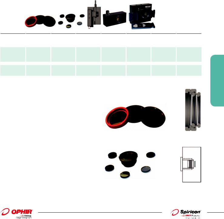
3.4.1 Neutral Density Attenuators/Filters
For almost all applications, the laser beam intensity is too high for the operating range of the CCD. Therefore ND glass attenuator filters are available to reduce the intensity to the proper level at the CCD. In general, either the LBF-50 attenuating filer set or a set of individual, stackable, screw on filters is recommended. These filters are carefully designed not to affect beam quality or cause interference effects. One stackable ND1 filter and 2 ND2 filters are supplied standard with each camera.
Model |
|
Stackable |
|
LBF-50 |
|
Continuously |
|
ATP-K Variable |
|
UV ND Filters |
|
Speciality Filter |
|
Speciality Filter |
|
|
ND Filters |
|
|
|
Variable |
|
Attenuator |
|
|
|
for 355nm |
|
for 1300nm |
|
|
ND1/ND2/ND3 |
|
|
|
|
|
|
|
|
|
|
|
|
|
|
|
|
|
|
|
|
|
|
|
|
|
|
|
Nominal ND value |
1,2,3 |
0.3, 0.7, 1, 2, 3, 4 |
1-6 continuously |
ND=1.7-4.6 |
0.3, 0.7, 1.0, 1.3, |
Pass 355nm, |
Pass 1300nm, |
|||||||
|
|
|
|
|
|
variable |
|
Max. ND: 7.4 (with |
1.7, 2.0, 2.3, 2.7, |
|
blocks 532nm & |
|
blocks <1100nm |
|
|
|
|
|
|
|
|
|
fixed 2.8 gray- |
3.0, 3.3, 3.7, 4.0, |
|
1064nm |
|
|
|
|
|
|
|
|
|
|
|
glass attenuator) |
4.3, 4.7, 5.0, 6.0 |
|
|
|
|
|
Clear aperture |
|
Ø19mm |
|
Ø12mm |
|
Ø20mm |
|
Ø15mm |
|
Ø20mm |
|
Ø19mm |
|
Ø19mm |
Damage |
|
5W/cm2 |
|
5W/cm2 |
|
5W/cm2 |
|
100mW/mm |
|
100W/cm2 CW, |
|
5W/cm2 |
|
5W/cm2 |
threshold |
|
no distortion |
|
no distortion |
|
no distortion |
|
no thermal |
|
10ns pulses, no |
|
no distortion |
|
no distortion |
|
|
|
|
|
|
|
|
lensing |
|
distortion |
|
|
|
|
Mounting |
|
C-Mount Threads |
|
C-Mount Threads |
|
C-Mount Threads |
|
C-Mount Threads |
|
C-Mount Threads |
|
C-Mount Threads |
|
C-Mount Threads |
Stackable ND filters
The individual filters come in three versions, the ND1 filter in the red housing with ~10% transmission in the visible, the ND2 filter in the black housing with ~1% transmission and the ND3 filter in the green housing with ~0.1% transmission. The individual filters can be screwed on top of each other and thus stacked.
They are set at a small wedge angle in the housing so as not to cause interference effects.
ND1, ND2 and ND3 stackable filters |
Stackable filter |
LBF-50 |
showing wedge |
|
3.4.1 Beam Analysis
The LBF-50 comes with a set of filters that are inserted into the flange shown, mounted on top of each other and secured.
A set of 6 filters is provided that can achieve attenuation anywhere from ND 0.3 to ND 8. The LBF-50 is especially useful for CS or
C mount cameras with the CCD recessed way below the surface. The filters are recessed into the camera thus saving thickness as shown in the illustration to the right.
LBF - 50 filter assembly |
LBF-50 on C mount camera |
183
For latest updates please visit our website: www.ophiropt.com/photonics |
|
01.04.2014 |

Transmission vs. Wavelength
These ”neutral density” or ND filters do not have a flat response in attenuation vs. wavelength. See the graph for typical transmission vs. wavelength characteristics.
Specifications |
|
|
|
|
|
|
|
|
|
Item |
|
ND1 / ND2 / ND3 |
|
LBF-50 |
|
|
|
|
|
|
|
|
|
|
|
|
|
|
|
Nominal ND (vis) |
1, 2, 3 |
0.3, 0.7, 1, 2, 3, 4 |
|
|
|
|
|
||
|
|
|
|
|
|||||
Clear Aperture |
|
Ø19mm |
|
Ø12mm |
|
|
|
|
|
|
|
|
|
|
|
|
|||
|
|
|
|
|
|
|
|||
Damage threshold |
|
5W/cm2 , 1J/cm2 for ns pulses |
|
|
|
|
|
||
Continuously Variable Attenuator
For maximum ease of use there is the continuously variable attenuator that can vary its attenuation over a very wide range just by pushing and pulling the filters laterally. The attenuator consists of two opposite wedges of ND glass. The surfaces are arranged so that no parallel surfaces face each other so as to eliminate interference effects. The variable attenuator uses the same C-mount thread as the other components so it can be combined with additional stackable filters and beam splitters, if necessary, as shown.
3.4.1 Beam Analysis
184
01.04.2014
|
|
|
Illustration of |
|
|
|
|
variable attenuator |
|
|
|
|
mounted with |
|
|
|
|
additional filter |
|
|
|
|
and beam splitters |
|
|
|
|
Beam Splitters |
|
Push/Pull to vary attenuation |
Additional filter |
|||
Attenuation Sliders |
||||
|
|
|
||
|
|
|
|
|
Specifications |
|
|
|
|
Item |
|
Variable attenuator |
|
|
|
|
|
|
|
Nominal ND (vis) |
|
1 - 6 continuously variable |
|
|
Aperture |
|
Ø20mm |
|
|
Optical quality |
|
2 waves in visible |
|
|
Damage threshold |
|
5W/cm2 , 1J/cm2 for ns pulses |
|
|
For latest updates please visit our website: www.ophiropt.com/photonics

ATP-K Variable Attenuator
This option makes beam profiling easy. The ATP-K attenuates your laser without ghost reflections or fringes and has a knob-operated variable wedge attenuator of ND 1.7–4.6, and comes with a fixed grayglass attenuator with ND 2.8.
The ATP-K is also designed to be used with the HP-XXX high power attenuators and beam splitters. Both types of attenuators attach directly to the ATP-K via C-mount. The ATP-K has simple reproducible attenuation settings, and has a wavelength range of 360 to 2500+ nm.
Figure 1 below shows the safe average power for negligible beam distortion from thermal lensing. Absorptive filters, such as used in the ATP-K have an upper power limit of approximately 100mW per mm beam diameter. For pulsed beams, Figure 2 shows the damage threshold for energy where breakage of the glass wedge may occur. This is approximately 5J per mm beam diameter. For lasers with power or energy levels above this the first stage of attenuation will need to come from our line of high power reflective attenuators.
Figure 1 – Safe average power for negligible beam distortion
Figure 2 – Point at which damage will occur with pulsed energy
ATP-K Specifications
Maximum Power/Energy Handling |
100 mW/mm beam diameter 100 mJ total avg. energy Damage threshold: 5J |
Note: Powerful laser sources may require additional attenuation prior to the beam’s exposure to Model ATP-K. Additional attenuation usually is achieved by use of high-power laser mirror attenuators or clean, high-quality quartz plates (recommended with slight wedge angles).
Wavelength Range |
360-2500+ nm Near flat response out to 1500nm |
Attenuation Range |
Variable filters: ND = 1.7 to 4.6 Maximum ND 7.4 (with fixed 2.8 gray-glass |
|
attenuator) |
Note: ND (optical density) = log (1/T) or T=10 (-ND) where T is the fraction of light transmitted. For example, an ND of 5 transmits 0.00001 or 0.001%.
Clear Aperture |
15mm diameter |
Dimensions |
94 (W) x 28 (H) x 43 (D) mm |
Thickness Tolerance |
±0.25mm |
Mounting |
C-mount |
Base Mount |
¼-20 |
High Power Attenuators
Our high-power laser mirror attenuator transmits <1%, and comes in a C-Mount threaded adapter ring. It is also AR coated for either straight on or 45° orientation.
Available standard configurations:
ֺHP-266 — Use for 266 ±50nm
ֺHP-355 — Use for 350 ±50nm
ֺHP-450 — Use for 450 ±50nm
ֺHP-600 — Use for 500–700nm
ֺHP-800 — Use for 700–900nm
ֺHP-1064 — Use for 1000–1100nm
Other wavelengths available upon request.
Note that if more than one reflective attenuator is required to reduce the beam power, one of them must be oriented 45° to the beam. Unlike absorptive attenuators, reflectors cannot be stacked, because they will form a laser cavity.
3.4.1 Beam Analysis
185
For latest updates please visit our website: www.ophiropt.com/photonics |
|
01.04.2014 |
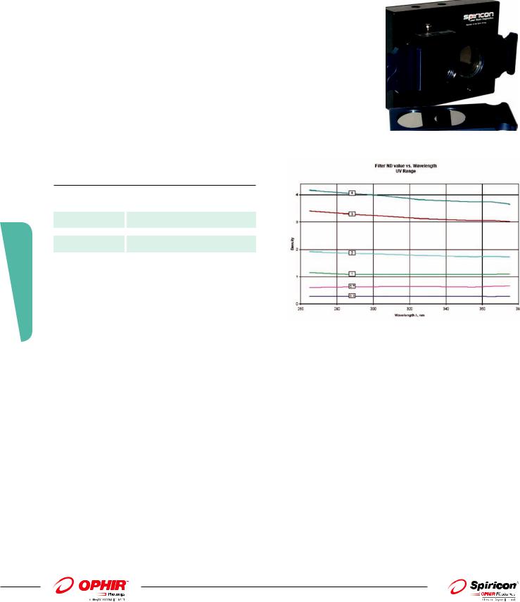
UV ND Filters
This accessory can be used with any camera fitted with C- mount threads. Simply thread the attenuator assembly into the front of the camera and then slide the ND filter arrays to get the desired amount of attenuation. This device can be used with laser outputs from microwatts to Watts. Three filter holders are provided with two filters in each holder. Each filter in the holder provides for a different value of attenuation. To use, slide the desired holder into the housing slot. A click is felt when the filter is properly aligned with the beam. The holders provided will allow for attenuation of up to ND 6.
C-mount interface for universal application to our CCD and Pyroelectric cameras 190-380nm attenuation covers Excimer, Helium Cadmium, and the Nd:YAG UV harmonic laser wavelengths. Attenuation with these ND filters permits the best use of the dynamic range of a beam profiling camera.
Attenuation range of 0.3 to 6.0 optical densities (ND). Set consists of three slides with two filters in each slide.
The Six Filters include 0.3, 0.7, 1.0, 2.0, 3.0 and 4.0 optical densities.
Two filters can be employed at one time for 0.3 – 6.0 optical attenuation in 0.3 or 0.4 ND steps. 20mm clear aperture will not vignette any of our applicable camera sensors.
Damage threshold = 100W/cm2 for CW lasers and 20mJ/cm2 for nano-second pulse width lasers.
Additional Beam Splitters can be added for attenuation of high power UV lasers.
UV attenuation system uses high quality optics from the leader in laser beam diagnostics.
3.4.1 Beam Analysis
186
Specifications |
|
|
Item |
|
UV ND Filters |
|
|
|
Nominal ND (UV) |
0.3, 0.7, 1.0, 1.3 ,1.7, 2.0, 2.3, 2.7, 3.0, 3.3, 3.7, |
|
|
4.0, 4.3, 4.7, 5.0, 6.0 |
|
Aperture |
|
Ø20mm |
Damage threshold |
|
100W/cm2 CW, 10ns pulses, no |
|
|
distortion |
Specialized Filters
There are also specialized filters available to eliminate extraneous wavelengths when measuring very short or very long wavelengths where the CCD cameras are not sensitive and the desired signal can get swamped by extraneous light of other wavelengths.
These filters are as follows:
1.The 355nm filter for monitoring the 3rd harmonic of YAG. This filter transmits 355nm but blocks 532nm and 1064nm.
2.The 1300nm filter transmits1300nm but blocks wavelengths shorter than 1100nm.
These filters are also on the same standard thread so they can be mixed with all the other components. See ordering information pages for more details.
01.04.2014 |
|
For latest updates please visit our website: www.ophiropt.com/photonics |
|
Ordering Information
Item
ND1 stackable filter (red housing)
ND2 stackable filter (black housing)
ND3 stackable filter (green housing)
LBF-50 filter set
Filter holder and 50x50 filter set
Variable filter
ATP-K
HP-266
HP-355
HP-450
HP-600
HP-800
HP-1064
UV ND Filters
Filter for 355nm-V2; give an undistorted image of the 355nm light
Filter for 1300nm
Description |
P/N |
4mm spacing screw on filter for camera with transmission of between 20% and 5% depending on spectral range. |
SPZ08234 |
Can be stacked and combined with other filters and beam splitters.. One filter is included with Spiricon cameras. |
|
4mm spacing screw on filter for camera with transmission of between 7% and 0.5% depending on spectral range. |
SPZ08235 |
Can be stacked and combined with other filters and beam splitters. Two filters are included with Spiricon cameras. |
|
4mm spacing screw on filter for camera with transmission of between 2% and 0.05% depending on spectral range. Can |
SPZ08253 |
be stacked and combined with other filters and beam splitters. |
|
Compact screw in filter holder with set of ND filters. Attenuations from low to 106. |
SP90081 |
Filter holder with set of 4 standard Schott 50X50mm neutral density filters. Useful to reduce intensity before |
SPZ08240 |
inputting into 4X beam reducer. Mounts to standard ¼” thread, ½” diameter laboratory rod. |
|
Continuously variable filter for complete control over beam intensity. Especially useful for pulsed lasers. Varies the |
SPZ17012 |
intensity over more than 4 orders of magnitude between wavelengths 350nm and 1100nm. Can be stacked and |
|
combined with other filters and beam splitters. |
|
Variable Attenuator Package provides smooth knob operated variable wedges with attenuation of optical density |
PH00128 |
(ND) 1.7–4.6 for a total attenuation capability of ND 7.4. Specially designed to eliminate ghost reflections, fringes, |
|
and light leaks. Small compact module including C-mount adapter to attach to camera, and C-mount receptacle |
|
to easily attach additional HP-series attenuators. |
|
High power laser grade fused silica reflective mirror attenuator for UV applications at 266nm. Second surface anti- |
PH00129 |
reflection coated. Transmits <1%. Useful 266 ±50nm. |
|
High power laser grade fused silica reflective mirror attenuator for UV applications at 355nm. Second surface anti- |
PH00130 |
reflection coated. Transmits <1%. Useful 355 ±50nm. |
|
High power laser mirror attenuator for applications in the visible from 400-500nm. Second surface anti-reflection |
PH00131 |
coated.Transmits <1%. Useful 450 ±50nm. |
|
High power laser mirror attenuator for applications in the visible from 500-700nm. Transmits <1%. |
PH00132 |
|
|
High power laser mirror attenuator for applications in the visible-Near IR from 700-900nm. Transmits <1%. |
PH00133 |
|
|
High power laser mirror attenuator for applications in the Near IR from 1000-1100nm. Transmits <1%. |
PH00134 |
|
|
3 Filters holders each with 2 inconel UV ND. |
SP90228 |
Filters for attunation up to ND 6. |
|
Silicon cameras can see the 355nm 3rd harmonic radiation of YAG. The YAG however usually emits some light at |
SPZ08246 |
532nm and 1064nm as well. This filter filters out the other 2 wavelengths to give undistorted image of the 355nm light. |
|
|
|
For all cameras that can operate at 1300nm but are quite insensitive there. This filter filters out all light below |
SPZ08242 |
1100nm to allow viewing 1300nm radiation without background interference. |
|
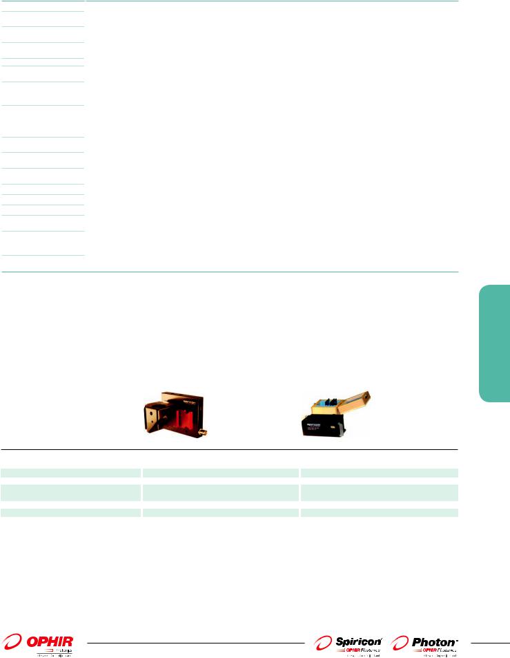
3.4.2 Beam Splitter + Neutral Density Filters Combo
The attenuators described before can provide a high degree of attenuation however, these neutral density attenuators cannot dissipate more than 5W or so. Therefore we often place beam splitters in front of the attenuators to reduce the intensity before the ND filters. These beam splitters are made of UV grade fused silica for use from 190 to 2000nm. Since they do not absorb light, they have a much higher power handling capacity than the ND attenuator/filters.
Model |
|
LBS-300 |
|
LBS-100 |
|
|
|
||
|
|
|
|
|
Wavelength |
multiple versions from 190 to 1550nm |
multiple versions; 400-900nm, 1064nm, 10.6µm |
||
Reflection |
|
0.01% of incident beam |
|
4% @ 400-900nm, 1% @1064nm, 0.5% or 5% @10.6µm |
Nominal ND value (vis) |
0.3, 0.7, 1, 2, 3, 4 |
|
0.3, 0.7, 1, 2, 3, 4 for 300-900nm & 1064nm 30% |
|
|
|
|
|
& 60% for 10.6µm |
Clear aperature |
|
Ø17.5mm |
|
Ø19mm |
Damage threshold |
|
see spec sheet |
|
5W/cm2 no distortion |
Mounting |
|
C-Mount Threads |
|
Lab post mounted |
|
|
|
|
|
3.4.2 Beam Analysis
187
For latest updates please visit our website: www.ophiropt.com/photonics |
|
|
|
01.04.2014 |

3.4.2 Beam Analysis
LBS-300 Beam Splitters
The LBS-300 beam splitter attachment for C-mount, CS-mount, or Ophir mount cameras allow you to measure laser beams with diameters up to 15mm and powers ranging from 10 mWatts to ~400 Watts. The beam sampler is designed so that the preferential polarization selection effect of a single wedge is cancelled out and the resulting beam image is polarization corrected to restore the polarization components of the original beam. The beam sampler operates by reflecting the incoming beam from the front surfaces of a pair of wedges through 90 degrees into the camera. Approximately 99% of the beam is transmitted through the beam sampler with 0.01% passed on to the camera. A set of adjustable ND filters are provided to make final intensity adjustments to the beam before it reaches the camera imager. As an option, you may order the WVF-300 (P/N SP90195) continuously variable ND filter set that can slide in and replace the fixed ND filters. If additional attenuation is needed, an external wedge (P/N SPZ17015) may be mounted at the input port, however this 3rd wedge will cause polarization selectivity when the beam is significantly polarized different in the S and P planes. Alternatively, two LBS-300s can be coupled in series providing up to a 10-8 attenuation.
Primary beam in
Primary beam out |
|
|
2 - 45° wedges to reflect |
Selection of 4 adjustable |
Optional SP90273 Large C-mount Wedge Splitter |
the primary beam into |
ND filters |
|
the camera |
|
|
Ordering Information
Model |
LBS-300-UV |
LBS-300-VIS |
LBS-300-NIR |
LBS-300-BB |
Part No. |
SP90183 |
SP90184 |
SP90185 |
SP90186 |
Wavelength |
266-355nm |
400-700nm |
1064nm |
190-1550nm |
Wedge Material |
UVFS |
BK7 |
BK7 |
UVFS |
Wedge Coating |
A/R ≤1% |
AR ≤1% |
AR ≤1% |
No coating, 4% reflection |
Clear aperture |
17.5mm |
17.5mm |
17.5mm |
17.5mm |
Reflection |
0.01% |
0.01% |
0.01% |
0.16% |
Wedge ND value, each |
ND ≥2 |
ND ≥2 |
ND ≥2 |
ND ~1.3 |
ND Filters |
Inconel |
Bulk ND |
Bulk ND |
One each of the UV, VIS & NIR sets |
ND Values, nominal |
0.3, 0.7, 1.0, 2.0, 3.0, 4.0 |
0.3, 0.7, 1.0, 2.0, 3.0, 4.0 |
0.3, 0.7, 1.0, 2.0, 3.0, 4.0 |
See UV, VIS and NIR |
|
(Blu holders) |
(Grn holders) |
(Red holders) |
descriptions |
Filter Slides |
3 |
3 |
3 |
9 |
Maximum allowable input |
100 W/cm2 CW |
50 W/cm2 |
50 W/cm2 |
See adjacent specifications |
to filter (1) |
20mJ/cm2, 10ns pulse |
1J/cm2, 10ns pulse |
1J/cm2, 10ns pulse |
|
Accessories |
|
|
|
|
Wedge Variable ND Filter kit |
N/A |
WVF-300 SP90195 |
WVF-300 SP90195 |
WVF-300 SP90195 |
Beam Dumps |
BD-040-A, 40 Watts Max Power, Air Cooled |
|
SP90192 |
|
|
BD-500-W, 500 Watts Max Power, Water Cooled |
|
SP90193 |
|
Beam Deflector Assemby |
for 400-1100 nm only |
|
|
SP90263 |
Large C-mount Wedge |
For additional attenuation add this to the front end of the LBS-300. Good for 350-2000nm |
SP90273 |
||
Splitter |
|
|
|
|
Note: (1) |
ND bulk absorbing filters damage threshold is 50W/cm2 but should be used at <5W/cm2 to avoid thermal lensing effects. |
|||
188
01.04.2014 |
|
For latest updates please visit our website: www.ophiropt.com/photonics |
|