

laser_measurement_instruments_catalog
.pdf3.2.4.5 900-1700nm - InGaAs NIR Cameras
Models XC-130 100Hz
Features
ֺNIR performance at room temperature
ֺHigh resolution InGaAs array: 320x256
ֺ60dB true system dynamic range
ֺExclusive Ultracal for ISO conforming accuracy
ֺAvailable with BeamGage software
XEVA 100Hz
75,09 |
106,5 |
43,7 |
|
12,31 |
90,5 |
110,7 |
31,68 49,8 86,05 |
64 |
55 |
87,4 |
|
USB Cameras for use with Laptop or Desktop PC
Model XEVA XC-130 |
|
Description |
|
|
|
Application |
NIR wavelengths, high resolution, ROI and binning |
|
Spectral response |
|
900-1700nm (consult factory for other options) |
Element pitch |
|
30µm square |
Number or elements |
|
320 x 256 |
Area |
|
9.6 x 7.6mm |
Lens |
|
C-mount, (Optional) |
Minimum system dynamic range |
|
low gain 68dB, high gain 60dB |
Saturation intensity |
|
1.3 uW/cm2 at 1550 nm |
Frame rate |
|
100 Hz (1) |
Non-uniformity correction |
|
2-Point correction plus bad pixel correction, NUC files provided |
Snap-shot mode |
|
Via external TTL trigger, cable provided |
Exposure control |
|
1us to 400 sec in Low Gain mode |
Imager Cooling |
|
Thermoelectric cooler plus forced convection |
Ambient operating temperature |
|
0 - 50° C |
Dimensions, mm, HxWxD |
|
111 x 87 x 107 mm |
Weight, camera head |
|
approx. 1.8 kg |
Software supported |
|
BeamGage |
PC interface |
|
USB 2.0, special cable provided |
Note: |
|
(1) The uncorrected rate, final corrected rate will be less. |
|
|
|
3.2.4.5 Beam Analysis
149
For latest updates please visit our website: www.ophiropt.com/photonics |
|
01.01.2014 |
3.2.5 13-355nm and 1.06-3000µm - Pyroelectric Array Camera
PyrocamTM III & Pyrocam IV Series
Features
ֺSpectral ranges available from 157 to 355 nm and 1.06 to >3000 µm
ֺImage CO2 lasers, telecom NIR lasers and other infrared sources out to Far IR THz sources
ֺSolid state array camera with 1000:1 linear dynamic range for accurate profiling
ֺIntegrated chopper for CW beams and thermal imaging
ֺInterchangeable windows available for a variety of applications
ֺIncludes BeamGage Laser Beam Analysis Software for quantitative analysis and image display
3.2.5 Beam Analysis
Pyrocam III |
Pyrocam IV |
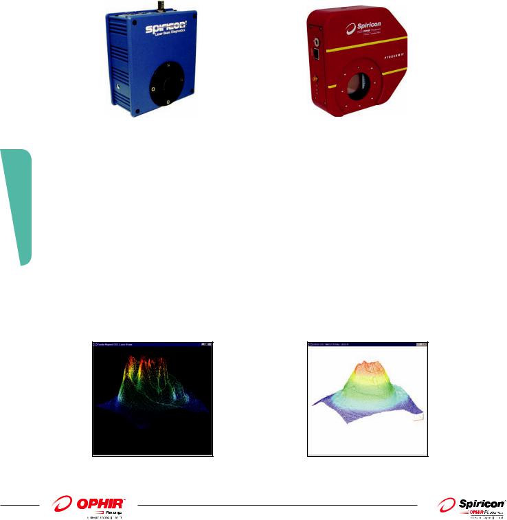
Spiricon has been the world leader in the manufacture of pyroelectric solid-state detector arrays and cameras. For over 25 years the PyrocamTM has been the overwhelming camera of choice for Laser Beam Diagnostics of IR and UV lasers and high temperature thermal imaging. Precision, stability, reliability, and versatility have become its proud heritage.
The PyrocamTM III offers a 1/2X1/2 inch detector array with easy Windows® camera setup, direct Windows quantitative and image display, 14 bit digitizer, versatile Firewire® PC interface, and an integral chopper for CW beams and thermal imaging.
The Pyrocam IV offers a 1 inch by 1 inch detector array with easy Windows® camera setup and quantitative image display through the BeamGage software, 16 bit digitizer, high-speed Gigabit Ethernet PC interface, and an integral chopper for CW beams and thermal imaging.
See Your Beam As Never Before
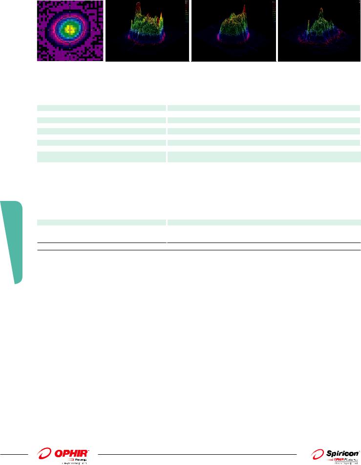
Both Pyrocam cameras create clear and illuminating images of your laser beam profile. Displayed in 2D or 3D views, you can immediately recognize beam characteristics that affect laser performance and operation. This instantly alerts you to detrimental laser variations. Instantaneous feedback enables timely correction and real-time tuning of laser parameters. For example, when an industrial shop foreman saw the CO2 laser beam profile in Figure 1 he knew immediately why that laser was not processing materials the same as the other shop lasers, that had similar profiles shown in Figure 2.
Fig. 1. Industrial CO2 laser performing inconsistent processing.
150
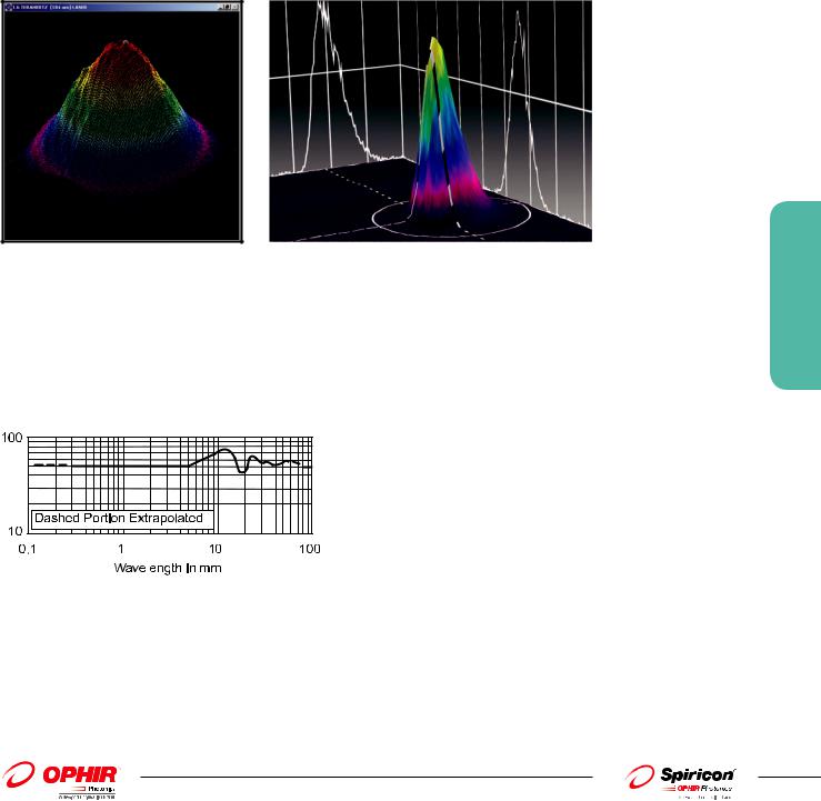
Fig. 2. Beam profile of industrial CO2 laser making consistently good product.
01.01.2014 |
|
For latest updates please visit our website: www.ophiropt.com/photonics |
|
Pulsed and CW Lasers
The Pyrocams measure the beam profile of both pulsed and CW lasers. Since the pyroelectric crystal is an integrating sensor, pulses from femtosecond to 12.8ms can be measured. The pyroelectric crystal only measures changes in intensity, and so is relatively immune to ambient temperature changes. Because CW laser beams must be chopped to create a changing signal, the Pyrocam contains an integral chopper, as an option.
Measuring Terahertz Beam Profiles
Spiricon’s Pyrocam pyroelectric cameras are an excellent tool for measuring THz lasers and sources. The coating of the crystal absorbs all wavelengths including 1µm to over 3000µm (0.1THz to 300THz). For THz sources the sensitivity of the Pyrocam is relatively low, at about 3mW/cm2 at full output. With a S/N of 1000, beams of 30mW/cm2 are easily visible.
In addition, with Spiricon’s patented Ultracal baseline setting, multiple frames can be summed to “pull” a signal out of the noise. Summing 256 frames enables viewing of beams as low as 1-2mW/cm2.
Pyrocam III imaging THz laser beam at 0.2THz |
Pyrocam IV imaging THZ laser beam 0.5 THz (5mm) 5mW input |
(1.55mm) 3mW input power; 19 frames summed |
power; single frame |
Broad Wavelength Response
The Pyrocam detector array has a very broadband coating which enables operation at essentially all IR and UV laser wavelengths. The curve ends at 100nm in the UV, but X-ray operation has been observed. Likewise the curve ends at 100µm in the far IR, but the camera has been used at >3000µm.
3.2.5 Beam Analysis
Fig. 6. Spectral response of PyrocamTM III detector array without window.
Thus you can use the Pyrocam in the near IR for Nd:YAG lasers at 1.06µm, and for infrared fiber optics at 1.3µm and 1.55µm. Use the Pyrocam for HF/DF lasers near 4µm and for Optical Parametric Oscillators from 1 µm to 10µm. It measures Free Electron Lasers between 193µm and 3000µm.
151
For latest updates please visit our website: www.ophiropt.com/photonics |
|
01.01.2014 |
3.2.5 Beam Analysis
152
Er:YAG laser at 2.9µm. |
Output of infrared fiber optic. |
THz laser beam at 1.6THz (184µm). |
Free Electron laser at 100µm. |
The Pyrocam is extremely useful in the UV from 355nm to 157nm for Excimer lasers and for tripled or quadrupled Nd:YAG lasers. The detector is stable under UV illumination, without the deterioration experienced by CCD cameras. (The pyroelectric detector operates in the visible spectrum, and can see the alignment HeNe used with CO2 lasers. However, spurious response from the underlying silicon multiplexer creates undesirable performance, and the camera is not recommended for quantitative visible measurements).
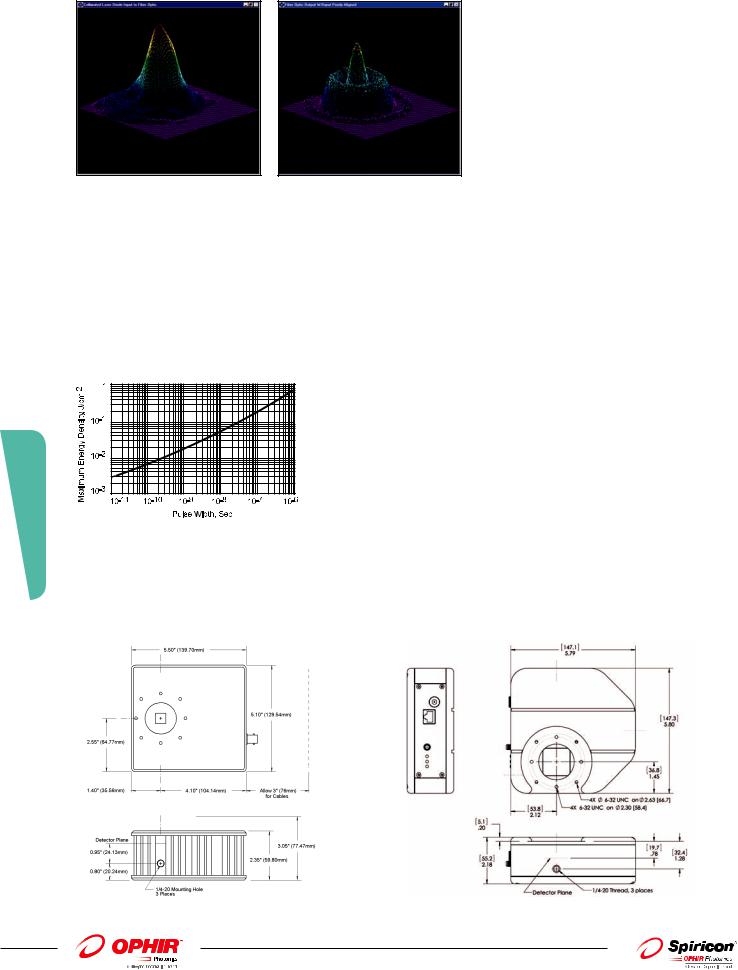
Windows® PC Interface
The PyrocamTM III Windows application incorporates setup software to control all functions of the camera, such as pulsed versus chopped operation, gain, and background reference subtraction, eliminating all controls from the camera housing.
PyrocamTM III Windows setup menu
This interface is not needed when using the Pyrocam IV.
BeamGage Image Analysis Software
Both Pyrocams come bundled with BeamGage, the state-of-the-art beam profiling system that performs rigorous data acquisition and analysis of laser beam parameters, such as beam size, shape, uniformity, divergence, mode content, and expected power distribution. Once the Pyrocam is connected to the PC and BeamGage is running, the software automatically detects the camera presence and is immediately ready to start taking images and displaying them on the monitor.
BeamGage recognizes the Pyrocam IV and allows you to quickly start analyzing your laser beam
01.01.2014 |
|
For latest updates please visit our website: www.ophiropt.com/photonics |
|

BeamGage is the industry’s first beam profiling software to be newly designed, from scratch, using the most advanced tools and technologies. BeamGage is based on UltraCal™, Spiricon’s patented baseline correction algorithm that helped establish the
ISO 11146-3 standard for beam measurement accuracy. BeamGage provides high accuracy results, guaranteeing the data baseline (zeropoint reference) is accurate to 1/8th of a digital count on a pixel-by-pixel basis.
BeamGage permits the user to employ custom calculations for best fit to an individual application. These user-defined computations are treated like the standard calculations. They can be displayed on the monitor, logged with results, and included in hard-copy reports.
The system also allows the user to configure the displayed calculations, set-up the screen layout, and password-protect the configuration. This permits secure product testing, ensures security in production environments where plant floor personnel interface with the system, and assures the validity of the data for Statistical Process Control (SPC).
Hybrid Integrated Circuit Sensor
The Pyrocam consists of a LiTa03 pyroelectric crystal mounted with indium bumps to a solid-state readout multiplexer. This sensor, developed as the Company’s core technology for the Pyrocam I, has proven to be the most rugged, stable, and precise IR detector array available. Light impinging on the pyroelectric crystal is absorbed and converted to heat, which creates charge on the surface. The multiplexer then reads out this charge. For use with short laser pulses, the firmware of the camera creates a very short electronic shutter to accurately capture the thermally generated signal.
PyrocamTM III sensor array and window assembly |
Pyrocam IV 25mm X 25mm array |
State-Of-The-Art Electronics
The camera features a high resolution A/D converter which digitizes deep into the camera noise. This enables reliable measurement and analysis of both large signals and low level signals in the wings of the laser beam. High resolution digitizing also enables accurate signal summing and averaging to pull weak signals out of noise. This is especially useful with fiber optics at 1.3µm and 1.55µm, and in thermal imaging.
Applications Of The PyrocamTM Ill
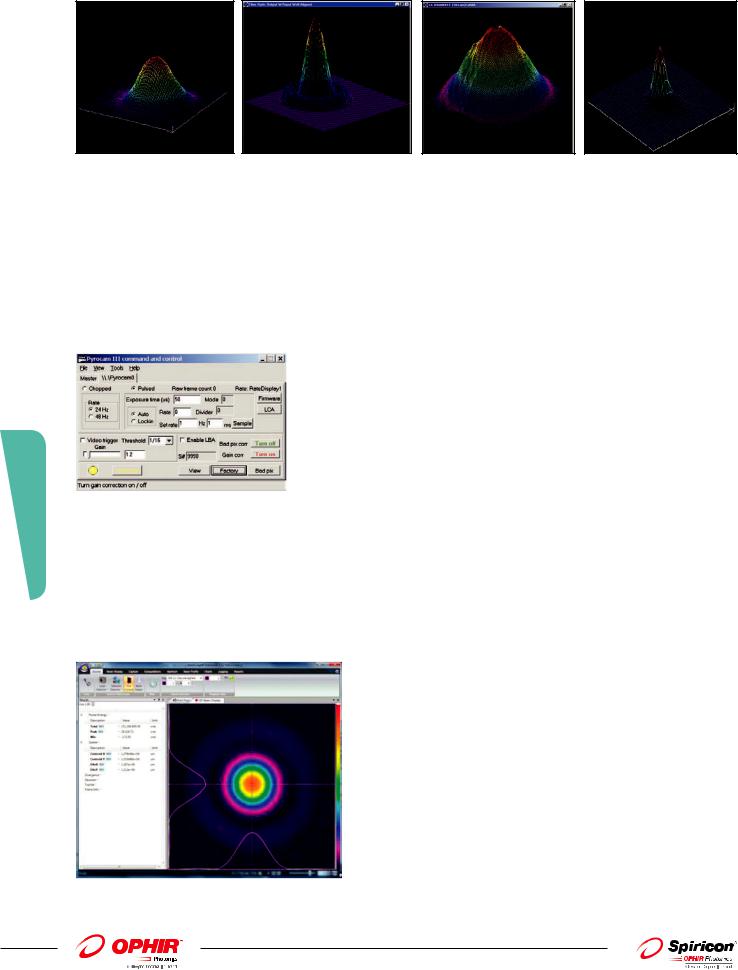
The Pyrocam is an ideal camera for use in scientific laboratory investigation of laser beams. This includes physics, chemistry, and electronic system designs. As an example, the photos below show
a research CO2 laser and a research Nd:YAG laser, both with cavity misalignment.
The camera is also useful in product engineering of CO2 and other infrared lasers. The Pyrocam is an integral part of the assembly lines of many CO2 laser manufacturers. Integrators of systems are
using the Pyrocam sensor to make sure that optical CO2 laser with cavity misalignment. Nd:YAG laser with cavity misalignment. systems are aligned and operating properly.
There are many medical applications of the Pyrocam, such as the analysis of excimer lasers used for eye surgery. In many cases these lasers need alignment to ensure that the eye surgery is performed as expected. Other medical IR lasers perform dermatology, for which the uniformity of the beam profile must be assured.
Fiber optic communications, at 1.3µm and 1.55µm make significant use of the Pyrocam for analyzing the beams being emitted, as well as analyzing properties of the beams before launching them into fibers. The greater stability of the Pyrocam make it a good choice over other cameras operating at telecommunication wavelengths.
3.2.5 Beam Analysis
153
For latest updates please visit our website: www.ophiropt.com/photonics |
|
01.01.2014 |
3.2.5 Beam Analysis
CO2 laser with cavity misalignment. |
Nd:YAG laser with cavity misalignment. |
The Pyrocam is becoming an essential tool in the maintenance of industrial infrared lasers, especially CO2. The Pyrocam replaces non-electronic mode burns and acrylic blocks by providing higher definition electronic recording of data, and analysis of short term fluctuations. The Pyrocam is superior to other electronic methods of measuring CO2 lasers because the entire beam can be measured in a single pulse, and additional measurements made in real-time. This ensures that the beam did not change during the measurement.
Detector Damage Threshold
The Pyrocam sensor is capable of operation with intensities about 100 times greater than CCD cameras. This makes the camera ideal for use with high power lasers, as less attenuation is required. Nevertheless, pulsed lasers with fluence too high can evaporate the absorbing front electrode.
Pulsed damage threshold of pyroelectric detector coating.
As shown the damage threshold increases with pulse width. With nanosecond and longer pulses, detector saturation occurs before damage. With shorter pulses it helps to increase the camera amplifier gain so that electronic saturation occurs before damage.
The sensor can be damaged by excessive CW power, which causes crystal cracking. Very few Pyrocam detectors have been damaged by CW power, but some have been ablated by high peak pulse energy.
Pyrocam III Dimensions |
Pyrocam IV Dimensions |
154
01.01.2014 |
|
For latest updates please visit our website: www.ophiropt.com/photonics |
|

Specifications
|
|
Pyrocam III |
|
Pyrocam IV |
Application |
|
UV and IR |
|
UV and IR |
Spectral response |
|
13 - 355nm |
|
13 - 355nm |
|
|
1.06 - 3000µm |
|
1.06 - 3000µm |
|
|
|
|
|
Interchangeable windows |
|
See selection in Ordering section |
|
See selection in Ordering section |
|
|
|
|
|
Detector array details |
|
|
|
|
Active area |
|
12.4mm x 12.4mm |
|
25.6mm x 25.6mm |
Element spacing |
|
100µm x 100µm |
|
80µm x 80µm |
Number of elements |
|
124 x 124 |
|
320 x 320 |
Pixel size |
|
85µm x 85µm |
|
75µm x 75µm |
CHOPPED CW OPERATION |
|
|
|
|
Chopping frequencies |
|
24Hz, 48Hz |
|
25Hz, 50Hz |
|
|
|
|
|
Sensitivity (RMS noise limit) |
|
220nW/pixel (24Hz) |
|
64nW/pixel (25Hz) |
|
|
320nW/pixel (48Hz) |
|
96nW/pixel (50Hz) |
|
|
2.2mW/cm2 (24Hz) |
|
1.0mW/cm2 (25Hz) |
|
|
3.2mW/cm2 (48Hz) |
|
1.5mW/cm2 (50Hz) |
|
|
|
|
|
Noise equivalent power (NEP) |
|
45nW/Hz1/2/pixel (1Hz) |
|
13nW/Hz1/2/pixel (1Hz) |
|
|
|
|
|
Saturation power |
|
2.2W/cm2(24Hz) |
|
3.0W/cm2(25Hz) |
|
|
3.2W/cm2 (48Hz) |
|
4.5W/cm2 (50Hz) |
|
|
|
|
|
Damage threshold power |
|
|
|
|
Over entire array |
|
2W |
|
2W |
Peak power density |
|
8W/cm2 |
|
8W/cm2 |
PULSED OPERATION |
|
|
|
|
Laser pulse rate |
|
Single-shot to 1000Hz |
|
Single-shot to 1000Hz |
|
|
|
|
|
Pulse width |
|
1fs - 12.8ms |
|
1fs - 12.8ms |
|
|
|
|
|
Sensitivity (peak noise limit) |
|
7nJ/pixel |
|
0.5nJ/pixel |
|
|
70µJ/cm2 |
|
8µJ/cm2 |
|
|
|
|
|
Saturation energy |
|
10mJ/cm2 |
|
15mJ/cm2 |
|
|
|
|
|
Damage threshold |
|
20mJ/cm2 (1ns pulse) |
|
20mJ/cm2 (1ns pulse) |
|
|
600mJ/cm2 (1 ms pulse) |
|
600mJ/cm2 (1 ms pulse) |
|
|
|
|
|
Trigger input |
|
|
|
|
High logic level |
|
3.0 - 6.0V |
|
3.0 - 6.0V |
Low logic level |
|
0 - 0.8V |
|
1 - 0.8V |
Pulse width |
|
4µs min |
|
4µs min |
OPERATING CONNECTIONS AND CONDITIONS |
|
|
|
|
Power |
|
100-240 VAC |
|
12VDC |
|
|
|
|
|
Line frequency |
|
60/50Hz External Supply |
- |
|
|
|
|
|
|
Power consumption |
|
10W |
|
12W |
|
|
|
|
|
Operating temperature |
|
5°C to 50°C |
|
5°C to 50°C |
PHYSICAL |
|
|
|
|
Case Dimensions |
|
140mm H X 130mm W X 60mm D |
|
147.3mm H X 147.1mm W X 55.2mm D |
Detector Position |
|
Centered in width |
|
53.8mm from bottom left |
|
|
35.6mm from bottom |
|
36.8mm from bottom |
|
|
15.2mm behind front cover (without included |
|
19.8mm behind front cover |
|
|
C-mount attached) |
|
|
|
|
|
|
|
Weight |
|
1.52Kg (3.25lbs) |
|
1.2kg (2.65lbs); not including power supply |
|
|
|
|
|
PC interface |
|
Two Firewire® interface ports (IEEE 1394a) |
|
Gigabit Ethernet (IEEE 802.3ab), GigE Vision compliant |
3.2.5 Beam Analysis
155
For latest updates please visit our website: www.ophiropt.com/photonics |
|
01.01.2014 |

3.2.5 Beam Analysis
|
|
Pyrocam III |
|
Pyrocam IV |
|
MEASUREMENTS PERFORMED |
|
|
|
|
|
Windows imaging viewer |
|
Total power or energy in digital counts or |
|
|
|
|
|
calibrated in software |
|
|
|
|
|
Peak power or energy in digital counts or |
|
|
|
|
|
calibrated in software |
|
|
|
|
|
Peak location in µm |
|
|
|
|
|
Centroid location in µm |
|
|
|
|
|
Diameter at 1/e2 points in µm |
|
|
|
|
|
X & Y Knife edge beam widths in µm |
|
|
|
|
|
|
|
||
Using BeamGage |
|
Extensive set of quantitative and image display capabilities. |
|
||
Array Quality |
|
See BeamGage data sheet. |
|
||
|
|
|
|
|
|
|
|
Grade A Up to 50 bad pixels, all correctable |
|
Grade A <300bad pixels, all correctable |
|
|
|
No uncorrectable clusters |
|
No uncorrectable clusters |
|
|
|
Grade B Up to 100 bad pixels |
|
|
|
|
|
No uncorrectable clusters within the 70% |
|
|
|
|
|
central area, no more than 2 outside |
|
|
|
Ordering Information
Item |
|
Description |
P/N |
|
|
Pyrocam III Beam Profiler Systems |
|
|
|
||
PY-III-P-A |
|
Pyroelectric array detector, pulsed only, Grade A, two FireWire ports, and basic viewer software. BeamGage |
SP90090 |
|
|
|
|
Standard included. To complete this order, you must add an Interchangeable Window part number to accompany |
|
|
|
|
|
this system (see below). |
|
|
|
PY-III-P-B |
|
Pyroelectric array detector, pulsed only, Grade B, two FireWire ports, and basic viewer software. BeamGage Standard |
SP90091 |
|
|
|
|
included. To complete this order, you must add an Interchangeable Window part number to accompany this system (see |
|
|
|
|
|
below). |
|
|
|
PY-III-C-A |
|
Pyroelectric array detector, chopped and pulsed, Grade A, two FireWire ports, and basic viewer software. |
SP90092 |
|
|
|
|
BeamGage Standard included. To complete this order, you must add an Interchangeable Window part number to |
|
|
|
|
|
accompany this system (see below). |
|
|
|
PY-III-C-B |
|
Pyroelectric array detector, chopped and pulsed, Grade B, two FireWire ports, and basic viewer software. |
SP90093 |
|
|
|
|
BeamGage Standard included. To complete this order, you must add an Interchangeable Window part number to |
|
|
|
|
|
accompany this system (see below). |
|
|
|
Interchangeable Windows for Pyrocam III (one included free with the purchase of a Pyrocam III Beam Profiler System) |
|
|
|
||
PY-III-W-BK7-1.064 |
|
Pyrocam III Window BK7 A/R coated to 1064nm |
SP90101 |
|
|
PY-III-W-Si-1.05-2.5 |
|
Pyrocam III Window Silicon A/R coated to 1.05 - 2.5µm |
SP90102 |
|
|
PY-III-W-Si-2.5-4 |
|
Pyrocam III Window Silicon A/R coated to 2.5 - 4µm |
SP90103 |
|
|
PY-III-W-Ge-3-5.5 |
|
Pyrocam III Window Germanium A/R coated to 3 - 5.5µm |
SP90104 |
|
|
PY-III-W-Ge-10.6 |
|
Pyrocam III Window Germanium A/R coated to 10.6µm |
SP90105 |
|
|
PY-III-W-Ge-8-12 |
|
Pyrocam III Window Germanium A/R coated to 8 - 12µm |
SP90106 |
|
|
PY-III-W-ZnSe-10.6 |
|
Pyrocam III Window Zinc Selenide A/R coated to 10.6µm |
SP90107 |
|
|
PY-III-W-ZnSe-2-5 |
|
Pyrocam III Window Zinc Selenide A/R coated to 2 - 5µm |
SP90108 |
|
|
PY-III-W-Poly-THz |
|
Pyrocam III Window Polyethylene uncoated for Tera-Hz wavelengths |
SP90208 |
|
|
|
|
|
|
||
Pyrocam IV Beam Profiler Systems |
|
|
|
||
PY-IV-P-A |
|
Pyroelectric array detector, pulsed only, Grade A, one Gigabit Ethernet port and BeamGage Standard included. |
SP90299 |
|
|
|
|
To complete this order, you must add an Interchangeable Window part number to accompany this system |
|
|
|
|
|
(see below). |
|
|
|
PY-IV-C-A |
|
Pyroelectric array detector, choppend and pulsed, Grade A, one Gigabit Ethernet port and BeamGage Standard |
SP90296 |
|
|
|
|
included. To complete this order, you must add an Interchangeable Window part number to accompany this |
|
|
|
|
|
system (see below). |
|
|
|
Interchangeable Windows for Pyrocam IV (one included free with the purchase of a Pyrocam III Beam Profiler System) |
|
|
|
||
PY_IV-W-BK7-1.064 |
|
Pyrocam IV window assembly, BK7, A/R coated for 1.064µm |
SP90301 |
|
|
PY-IV-W-SI-1.05-2.5 |
|
Pyrocam IV window assembly, Si, A/R coated for 1.05 to 2.5µm |
SP90302 |
|
|
PY-IV-W-SI-2.5-4 |
|
Pyrocam IV window assembly, Si, A/R coated for 2.5 to 4µm |
SP90303 |
|
|
PY-IV-W-GE-3-5.5 |
|
Pyrocam IV window assembly, Ge, A/R coated for 3 to 5.5µm |
SP90304 |
|
|
PY-IV-W-GE-10.6 |
|
Pyrocam IV window assembly, Ge, A/R coated for 10.6µm |
SP90305 |
|
|
PY-IV-W-GE-8-12 |
|
Pyrocam IV window assembly, Ge, A/R coated for 8 to 12µm |
SP90306 |
|
|
PY-IV-W-ZNSE-10.6 |
|
Pyrocam IV window assembly, ZnSe, A/R coated for 10.6µm |
SP90307 |
|
|
PY-IV-W-ZNSE-2-5 |
|
Pyrocam IV window assembly, ZnSe, A/R coated for 2 to 5µm |
SP90308 |
|
|
PY-IV-W-POLY-THZ |
|
Pyrocam IV window assembly, LDPE, uncoated for Terahertz wavelengths |
SP90309 |
|
|
156
01.01.2014 |
|
For latest updates please visit our website: www.ophiropt.com/photonics |
|
3.2.5.1 YAG Focal Spot Analyzer
ֺImage focal spots down to 25µm in size
ֺFor laser powers up to 400W (additional external ND filters required)
ֺMeasure how focal distance shifts with power
ֺCan measure systems with focal length as short as 50mm
ֺModular design allows flexibility in use
ֺC-mount, compact laser beam sampler/attenuator for camera based laser beam profiling systems
ֺHigh damage threshold optics for measuring energetic sources
ֺProduces undistorted sample of laser under test
ֺAdjustable attenuation maximizes system dynamic range
ֺUp to 1 x 10⁻¹⁰ attenuation available (without external filters)
Measure the focal spot of a relatively high power laser, in particular a YAG laser. The average power can be from <1 to 400 Watts and the focal spot can be as small as 25µm. The FSA can also be used to measure how the focal spot shifts with power.
The lasers focal length from the lens to the focal spot is usually on the order of 70 to 120mm. The YAG FSA assembly adds a negative lens to the LBS-300 beam splitter assembly to increase the focal path and at the same time enlarge the image. Several focal length lenses are available to accommodate different host system focal paths. The FSA includes; user selectable negative lens, 2 beam splitters, a removable beam block on the 2nd splitter, and user selectable attenuation filters prior to the beam entering the camera. An excel spreadsheet is downloadable from our website that calculates which lenses are available to use for your application, how far to mount the FSA from your focusing lens in order to see the focal spot and what the magnification of the image will be.
Operation:
The FSA is mounted to the camera as shown. Then the assembly is placed below the final focusing lens of the laser at the recommended distance. The focal spot is found by moving the assembly closer and farther from the beam until the smallest spot size is seen. The exact magnification factor (usually 2-3 times) is calculated by moving the stage holding the FSA assembly a given lateral distance and seeing how far the centroid of the focal spot moves in the beam profiling software. This scaling factor is then entered into the software. In order to find focal spot shift with laser power, simply find focal spot at one power, change the power and measure how far the stage has to be moved up or down to get to the smallest beam size again.
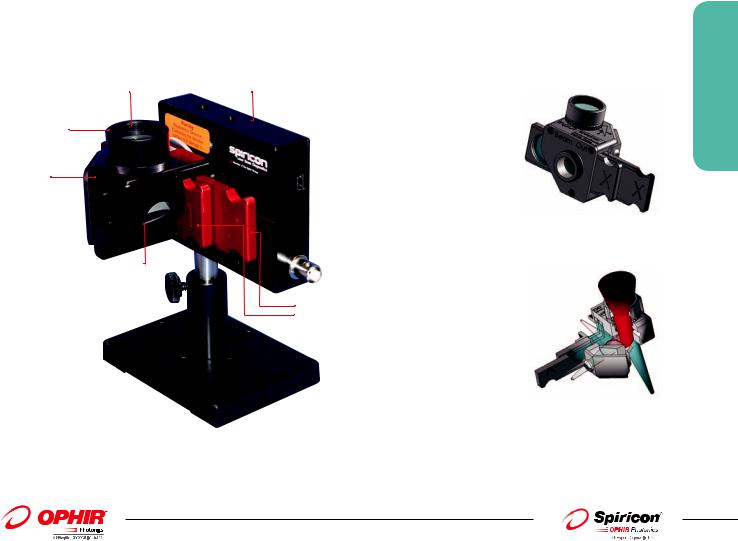
Incoming Beam |
Camera |
Negative lens
LBS-300
2nd Output 
 Beam; built-in
beam block
1st Output Beam; either to power meter or to Beam Dump
User selectable ND filters for attenuating input to the camera
Focal Spot Assembly Looking from camera mounting position
Focal Spot Assembly showing various beam paths
3.2.5.1 Beam Analysis
157
For latest updates please visit our website: www.ophiropt.com/photonics |
|
01.01.2014 |
Examples of Usage
3.2.5.1 Beam Analysis
158
65µm diameter focal spot |
|
Focal spot shape changing with laser power level |
||
Specifications |
|
|
|
|
|
|
|
|
|
Model |
|
YAG Focal Spot Analyzer |
||
|
|
|
|
|
Wavelength |
1064nm |
|||
Wedge Material |
|
BK7 |
||
Wedge Coating |
|
AR ≤1% |
||
Clear aperture |
|
17.5mm |
||
Wedge ND value, each |
|
ND ≥2 |
||
ND Filters |
|
Bulk ND |
||
ND Values, nominal |
|
0.3, .7, 1.0, 2.0, 3.0, 4.0 (Red holders) |
||
Filter Slides |
3 |
|
|
|
Filter Damage (1) |
|
50 W/cm2 |
||
|
|
1J/cm2, 10ns pulse |
||
Negative Lens |
|
FSA-50Y |
||
To add FSA capability |
|
-50mm YAG |
|
|
|
|
FSA-100Y |
|
|
|
|
-100mm YAG |
|
|
|
|
FSA-125Y |
|
|
|
|
-125mm YAG |
|
|
|
|
FSA-150Y |
|
|
|
|
-150mm YAG |
|
|
|
|
FSA-200Y |
|
|
Accessories |
|
-200mm YAG |
|
|
|
|
|
|
|
Variable Wedge ND Filter kit |
|
WVF-300 |
||
Beam Dumps |
|
BD-040-A, 40 Watts Max Power, Air Cooled |
|
|
|
|
BD-500-W, 500 Watts Max Power, Water Cooled |
|
|
Note: (1) ND bulk absorbing filters damage threshold is 50W/cm2 but should be used at <5W/cm2 to avoid thermal lensing effects.
Ordering Information
Item |
|
Description |
|
P/N |
|
|
|
|
|
YAG Focal Spot Analyzer |
|
|
|
|
YAG Focal Spot Analyzer assembly requires 1 each LBS-300-NIR and 1 each Negative Lens |
|
|
||
LBS-300-NIR |
|
Beam splitter and attenuators; beam split 2 times |
|
SP90185 |
FSA-50Y |
|
Negative lens; -50 mm YAG |
|
SP90187 |
FSA-100Y |
|
Negative lens; -100 mm YAG |
|
SP90188 |
FSA-125Y |
|
Negative lens; -125 mm YAG |
|
SP90189 |
FSA-150Y |
|
Negative lens; -150 mm YAG |
|
SP90190 |
FSA-200Y |
|
Negative lens; -200 mm YAG |
|
SP90191 |
Accessories |
|
|
|
|
WVF-300 |
|
ND filters; variable wedge. Replaces fixed value filter slides |
|
SP90195 |
BD-040-A |
|
Beam Dump; 40 Watts max. power, air cooled |
|
SP90192 |
BD-500-W |
|
Beam Dump; 500 Watts max. power, water cooled |
|
SP90193 |
|
|
|
|
|
01.01.2014 |
|
For latest updates please visit our website: www.ophiropt.com/photonics |
|