

III. Supply synonyms for the following words:
to perform, female thread, male thread, construction, instrument, form
IV. Give derivatives from the following words and translate them into Russian:
to operate, to perform, to cut, to construct, to thread, to tap, to fasten, usual, to hold
V. Supply antonyms for the following words:
straight grooves, manual tapping, final, to coincide
VI. Translate the following sentences observing different meanings of the word machine:
1. This machine is mainly used for removing large pieces of metal. 2, The engineer explained in his lecture how to machine workpieces of different shapes and sizes. 3. The size and shape of all machine parts should be checked by means of different measuring tools.
VII. Make up questions to which the italicized words are the answers:
1. With mechanical tapping in cast iron, bronze, brass, copper, and aluminium one tap is used. 2. When steel is tapped a set of two tools is used. 3. Before cutting threads the tap should be firmly set in a tap wrench. 4. A threading die is made of internally threaded flat steel stock.
VIII. Describe Figs 23 and 24 orally using the following words and word-combinations:
the tap, to be made, a cylindrical bar stock, to consist, the working part, the shank, to be used, fastening the threading tool, in a chuck or in a tap wrench, two or three taps, to be applied, manual tapping, the first and the second taps, to serve, to cut threads, the third tap, final thread cutting
IX. Giving answers to the following questions describe the threading die shown in Fig. 25:
1. What operations are performed with a threading die? 2. What material is a threading die made of? 3. How is a threading die threaded? 4. What is there between the cutting grooves of a threading die?
9. METHODS OF HOLDING WORKS BETWEEN CENTRES
When machining a piece of work on a lathe the former is usually mounted between the lathe centres. Having been mounted on the lathe the work is supported by the conical points of the live and dead centres. The work must therefore have centre holes in each end drilled by using a combined drill and a countersink. The size of the centre hole has to be proportioned to the weight of the work and the size of cut to be taken. By virtue of the clearance holes the work does not rest on the extreme points of the centres. This is important because otherwise the position of the work will be indefinite. Owing to this method of holding work between centres, the work can be removed from the lathe as often as may be desired. If the work has to be mounted again between centres for further treatment, it will rotate about the same axis as before.
The two lathe centres are mounted in two spindles: one — the live centre is held in the headstock spindle and turns together with the spindle and the work, the other— the dead centre is held in the tailstock spindle and in most cases does not turn and rubs against the work piece. The point of the dead centre should be hardened to prevent its wearing during the operations performed on the lathe. Both lathe centres should always be aligned, i. e. the points are to meet when the tailstock with its centre is moved up to the headstock centre. A turner tests the alignment of the centres by taking a cut and then measuring both ends of the cut by a micrometer. Having got the same measurements, the turner may be sure that the centres are aligned and he may proceed with the turning. The centre shown in Fig. 26 consists of a cone, on which the work to be treated is installed, and of a tapered shank, which fits corresponding taper holes in the headstock spindle and tailstock poppet.

Fig. 26. Centre:
1 — cone; 2 — tapered shank
When works are machined at high speeds or when the former are too heavy a dead centre and the work will be heated up so as to cause excessive wear from friction. In such cases the so called "running centres" are used. Fig. 27 shows a running centre inserted into the taper hole of the tailstock poppet. The centre rotates on ball bearings. The thrust exerted on the centre is taken by the available ball thrust bearing. The tapered shank fits the taper hole of the tailstock poppet.
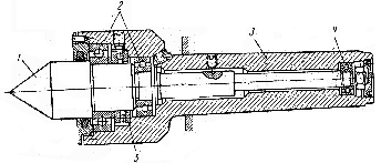 Fig.
27. Running Centre:
Fig.
27. Running Centre:
1 — centre; 2, 4 — ball bearings; 3 — tapered shank; 5 — ball thrust bearing
Exercises