

Mechanical_Intro_14.5_L04_Meshing
.pdf F. Submodeling
Submodeling is a technique where a coarsely meshed model can be solved followed by a subsequent solution using only a portion of the coarse model with a more refined mesh. Submodeling is available for structural and thermal analysis types with solid geometry.
As shown in the example below, and explained shortly, one of the key concepts in submodeling is the designation of the “cut boundaries” defining the submodel.
Cut Boundaries
41 |
© 2012 ANSYS, Inc. |
December 19, 2012 |
Release 14.5 |

 . . . Submodeling
As the figures below show, the displacements from the coarse model are mapped to the cut boundary locations on the submodel from the corresponding locations on the full model.
•Note, if the cut boundaries are too close to the stress concentrations the accuracy of the submodel can be degraded. A results comparison can be used to verify the cut boundary location (detailed in an upcoming example).
|
|
Submodel |
Full (coarse) Model |
|
|
|
|
|
42 |
© 2012 ANSYS, Inc. |
December 19, 2012 |
Release 14.5 |

 . . . Submodeling
Submodeling Example:
•The model shown below is initially solved using a coarse mesh.
•As expected we see stress concentrations in regions containing detailed geometry along with a coarse mesh.
•Based on these results we choose to create a submodel to explore the region circled in more detail.
43 |
© 2012 ANSYS, Inc. |
December 19, 2012 |
Release 14.5 |

 . . . Submodeling
Although there are numerous geometry modeling techniques that can be used to create the submodel, we have chosen to slice a body from the full model using the DesignModeler application. This new body is our submodel and a more refined mesh is created in the Mechanical application.
44 |
© 2012 ANSYS, Inc. |
December 19, 2012 |
Release 14.5 |

 . . . Submodeling
The submodel schematic is set up as shown here:
Original Full Model
Since the full model and submodel are comprised of different geometry, we can’t simply drag and drop a new structural system on to the existing one as this would link the geometry. Instead we create a new stand alone system and drag the full model solution onto the submodel’s setup cell.
45 |
© 2012 ANSYS, Inc. |
December 19, 2012 |
Release 14.5 |

 . . . Submodeling
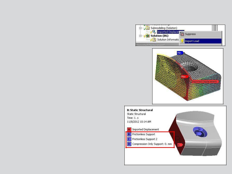
After opening the new (submodel) system open in Mechanical we can see a new “Submodeling” branch has automatically been inserted in the tree. If we RMB we can choose the type of result to import (displacement in this example).
In the details of the imported load we choose scope to which the loads are applied. The scope here is the cut boundaries of the submodel.
Note, there are numerous mapping options available when transferring loads not all of which will apply to submodeling. For a complete discussion see the section of the documentation covering “External Data Import”.
46 |
© 2012 ANSYS, Inc. |
December 19, 2012 |
Release 14.5 |
 . . . Submodeling
RMB to import the load from the full model. When completed, the import can be reviewed graphically.
Add any additional boundary conditions to the submodel to match those on the full model and solve.
47 |
© 2012 ANSYS, Inc. |
December 19, 2012 |
Release 14.5 |

 . . . Submodeling
To insure that the cut boundary is far enough from the high stress region a check should be performed to compare full and submodel results near the cut boundary.
Here an array of probes is used but path plots, surface plots, etc. are options as well. We simply want to verify that the results near the cut boundary are not drastically different between the full and sub models. If they are, it is usually an indication that the boundary needs to be moved further from the high stress region.
Full Model
Submodel
48 |
© 2012 ANSYS, Inc. |
December 19, 2012 |
Release 14.5 |