

- •1. INTRODUCTION
- •1.1 BASIC TERMINOLOGY
- •1.2 EXAMPLE SYSTEM
- •1.3 SUMMARY
- •1.4 PRACTICE PROBLEMS
- •2. TRANSLATION
- •2.1 INTRODUCTION
- •2.2 MODELING
- •2.2.1 Free Body Diagrams
- •2.2.2 Mass and Inertia
- •2.2.3 Gravity and Other Fields
- •2.2.4 Springs
- •2.2.5 Damping and Drag
- •2.2.6 Cables And Pulleys
- •2.2.7 Friction
- •2.2.8 Contact Points And Joints
- •2.3 SYSTEM EXAMPLES
- •2.4 OTHER TOPICS
- •2.5 SUMMARY
- •2.6 PRACTICE PROBLEMS
- •2.7 PRACTICE PROBLEM SOLUTIONS
- •2.8 ASSIGNMENT PROBLEMS
- •3. ANALYSIS OF DIFFERENTIAL EQUATIONS
- •3.1 INTRODUCTION
- •3.2 EXPLICIT SOLUTIONS
- •3.3 RESPONSES
- •3.3.1 First-order
- •3.3.2 Second-order
- •3.3.3 Other Responses
- •3.4 RESPONSE ANALYSIS
- •3.5 NON-LINEAR SYSTEMS
- •3.5.1 Non-Linear Differential Equations
- •3.5.2 Non-Linear Equation Terms
- •3.5.3 Changing Systems
- •3.6 CASE STUDY
- •3.7 SUMMARY
- •3.8 PRACTICE PROBLEMS
- •3.9 PRACTICE PROBLEM SOLUTIONS
- •3.10 ASSIGNMENT PROBLEMS
- •4. NUMERICAL ANALYSIS
- •4.1 INTRODUCTION
- •4.2 THE GENERAL METHOD
- •4.2.1 State Variable Form
- •4.3 NUMERICAL INTEGRATION
- •4.3.1 Numerical Integration With Tools
- •4.3.2 Numerical Integration
- •4.3.3 Taylor Series
- •4.3.4 Runge-Kutta Integration
- •4.4 SYSTEM RESPONSE
- •4.4.1 Steady-State Response
- •4.5 DIFFERENTIATION AND INTEGRATION OF EXPERIMENTAL DATA
- •4.6 ADVANCED TOPICS
- •4.6.1 Switching Functions
- •4.6.2 Interpolating Tabular Data
- •4.6.3 Modeling Functions with Splines
- •4.6.4 Non-Linear Elements
- •4.7 CASE STUDY
- •4.8 SUMMARY
- •4.9 PRACTICE PROBLEMS
- •4.10 PRACTICE PROBLEM SOLUTIONS
- •4.11 ASSIGNMENT PROBLEMS
- •5. ROTATION
- •5.1 INTRODUCTION
- •5.2 MODELING
- •5.2.1 Inertia
- •5.2.2 Springs
- •5.2.3 Damping
- •5.2.4 Levers
- •5.2.5 Gears and Belts
- •5.2.6 Friction
- •5.2.7 Permanent Magnet Electric Motors
- •5.3 OTHER TOPICS
- •5.4 DESIGN CASE
- •5.5 SUMMARY
- •5.6 PRACTICE PROBLEMS
- •5.7 PRACTICE PROBLEM SOLUTIONS
- •5.8 ASSIGNMENT PROBLEMS
- •6. INPUT-OUTPUT EQUATIONS
- •6.1 INTRODUCTION
- •6.2 THE DIFFERENTIAL OPERATOR
- •6.3 INPUT-OUTPUT EQUATIONS
- •6.3.1 Converting Input-Output Equations to State Equations
- •6.3.2 Integrating Input-Output Equations
- •6.4 DESIGN CASE
- •6.5 SUMMARY
- •6.6 PRACTICE PROBLEMS
- •6.7 PRACTICE PROBLEM SOLUTIONS
- •6.8 ASSGINMENT PROBLEMS
- •6.9 REFERENCES
- •7. ELECTRICAL SYSTEMS
- •7.1 INTRODUCTION
- •7.2 MODELING
- •7.2.1 Resistors
- •7.2.2 Voltage and Current Sources
- •7.2.3 Capacitors
- •7.2.4 Inductors
- •7.2.5 Op-Amps
- •7.3 IMPEDANCE
- •7.4 EXAMPLE SYSTEMS
- •7.5 ELECTROMECHANICAL SYSTEMS - MOTORS
- •7.5.1 Permanent Magnet DC Motors
- •7.5.2 Induction Motors
- •7.5.3 Brushless Servo Motors
- •7.6 FILTERS
- •7.7 OTHER TOPICS
- •7.8 SUMMARY
- •7.9 PRACTICE PROBLEMS
- •7.10 PRACTICE PROBLEM SOLUTIONS
- •7.11 ASSIGNMENT PROBLEMS
- •8. FEEDBACK CONTROL SYSTEMS
- •8.1 INTRODUCTION
- •8.2 TRANSFER FUNCTIONS
- •8.3 CONTROL SYSTEMS
- •8.3.1 PID Control Systems
- •8.3.2 Manipulating Block Diagrams
- •8.3.3 A Motor Control System Example
- •8.3.4 System Error
- •8.3.5 Controller Transfer Functions
- •8.3.6 Feedforward Controllers
- •8.3.7 State Equation Based Systems
- •8.3.8 Cascade Controllers
- •8.4 SUMMARY
- •8.5 PRACTICE PROBLEMS
- •8.6 PRACTICE PROBLEM SOLUTIONS
- •8.7 ASSIGNMENT PROBLEMS
- •9. PHASOR ANALYSIS
- •9.1 INTRODUCTION
- •9.2 PHASORS FOR STEADY-STATE ANALYSIS
- •9.3 VIBRATIONS
- •9.4 SUMMARY
- •9.5 PRACTICE PROBLEMS
- •9.6 PRACTICE PROBLEM SOLUTIONS
- •9.7 ASSIGNMENT PROBLEMS
- •10. BODE PLOTS
- •10.1 INTRODUCTION
- •10.2 BODE PLOTS
- •10.3 SIGNAL SPECTRUMS
- •10.4 SUMMARY
- •10.5 PRACTICE PROBLEMS
- •10.6 PRACTICE PROBLEM SOLUTIONS
- •10.7 ASSIGNMENT PROBLEMS
- •10.8 LOG SCALE GRAPH PAPER
- •11. ROOT LOCUS ANALYSIS
- •11.1 INTRODUCTION
- •11.2 ROOT-LOCUS ANALYSIS
- •11.3 SUMMARY
- •11.4 PRACTICE PROBLEMS
- •11.5 PRACTICE PROBLEM SOLUTIONS
- •11.6 ASSIGNMENT PROBLEMS
- •12. NONLINEAR SYSTEMS
- •12.1 INTRODUCTION
- •12.2 SOURCES OF NONLINEARITY
- •12.3.1 Time Variant
- •12.3.2 Switching
- •12.3.3 Deadband
- •12.3.4 Saturation and Clipping
- •12.3.5 Hysteresis and Slip
- •12.3.6 Delays and Lags
- •12.4 SUMMARY
- •12.5 PRACTICE PROBLEMS
- •12.6 PRACTICE PROBLEM SOLUTIONS
- •12.7 ASIGNMENT PROBLEMS
- •13. ANALOG INPUTS AND OUTPUTS
- •13.1 INTRODUCTION
- •13.2 ANALOG INPUTS
- •13.3 ANALOG OUTPUTS
- •13.4 NOISE REDUCTION
- •13.4.1 Shielding
- •13.4.2 Grounding
- •13.5 CASE STUDY
- •13.6 SUMMARY
- •13.7 PRACTICE PROBLEMS
- •13.8 PRACTICE PROBLEM SOLUTIONS
- •13.9 ASSIGNMENT PROBLEMS
- •14. CONTINUOUS SENSORS
- •14.1 INTRODUCTION
- •14.2 INDUSTRIAL SENSORS
- •14.2.1 Angular Displacement
- •14.2.1.1 - Potentiometers
- •14.2.2 Encoders
- •14.2.2.1 - Tachometers
- •14.2.3 Linear Position
- •14.2.3.1 - Potentiometers
- •14.2.3.2 - Linear Variable Differential Transformers (LVDT)
- •14.2.3.3 - Moire Fringes
- •14.2.3.4 - Accelerometers
- •14.2.4 Forces and Moments
- •14.2.4.1 - Strain Gages
- •14.2.4.2 - Piezoelectric
- •14.2.5 Liquids and Gases
- •14.2.5.1 - Pressure
- •14.2.5.2 - Venturi Valves
- •14.2.5.3 - Coriolis Flow Meter
- •14.2.5.4 - Magnetic Flow Meter
- •14.2.5.5 - Ultrasonic Flow Meter
- •14.2.5.6 - Vortex Flow Meter
- •14.2.5.7 - Positive Displacement Meters
- •14.2.5.8 - Pitot Tubes
- •14.2.6 Temperature
- •14.2.6.1 - Resistive Temperature Detectors (RTDs)
- •14.2.6.2 - Thermocouples
- •14.2.6.3 - Thermistors
- •14.2.6.4 - Other Sensors
- •14.2.7 Light
- •14.2.7.1 - Light Dependant Resistors (LDR)
- •14.2.8 Chemical
- •14.2.8.2 - Conductivity
- •14.2.9 Others
- •14.3 INPUT ISSUES
- •14.4 SENSOR GLOSSARY
- •14.5 SUMMARY
- •14.6 REFERENCES
- •14.7 PRACTICE PROBLEMS
- •14.8 PRACTICE PROBLEM SOLUTIONS
- •14.9 ASSIGNMENT PROBLEMS
- •15. CONTINUOUS ACTUATORS
- •15.1 INTRODUCTION
- •15.2 ELECTRIC MOTORS
- •15.2.1 Basic Brushed DC Motors
- •15.2.2 AC Motors
- •15.2.3 Brushless DC Motors
- •15.2.4 Stepper Motors
- •15.2.5 Wound Field Motors
- •15.3 HYDRAULICS
- •15.4 OTHER SYSTEMS
- •15.5 SUMMARY
- •15.6 PRACTICE PROBLEMS
- •15.7 PRACTICE PROBLEM SOLUTIONS
- •15.8 ASSIGNMENT PROBLEMS
- •16. MOTION CONTROL
- •16.1 INTRODUCTION
- •16.2 MOTION PROFILES
- •16.2.1 Velocity Profiles
- •16.2.2 Position Profiles
- •16.3 MULTI AXIS MOTION
- •16.3.1 Slew Motion
- •16.3.1.1 - Interpolated Motion
- •16.3.2 Motion Scheduling
- •16.4 PATH PLANNING
- •16.5 CASE STUDIES
- •16.6 SUMMARY
- •16.7 PRACTICE PROBLEMS
- •16.8 PRACTICE PROBLEM SOLUTIONS
- •16.9 ASSIGNMENT PROBLEMS
- •17. LAPLACE TRANSFORMS
- •17.1 INTRODUCTION
- •17.2 APPLYING LAPLACE TRANSFORMS
- •17.2.1 A Few Transform Tables
- •17.3 MODELING TRANSFER FUNCTIONS IN THE s-DOMAIN
- •17.4 FINDING OUTPUT EQUATIONS
- •17.5 INVERSE TRANSFORMS AND PARTIAL FRACTIONS
- •17.6 EXAMPLES
- •17.6.2 Circuits
- •17.7 ADVANCED TOPICS
- •17.7.1 Input Functions
- •17.7.2 Initial and Final Value Theorems
- •17.8 A MAP OF TECHNIQUES FOR LAPLACE ANALYSIS
- •17.9 SUMMARY
- •17.10 PRACTICE PROBLEMS
- •17.11 PRACTICE PROBLEM SOLUTIONS
- •17.12 ASSIGNMENT PROBLEMS
- •17.13 REFERENCES
- •18. CONTROL SYSTEM ANALYSIS
- •18.1 INTRODUCTION
- •18.2 CONTROL SYSTEMS
- •18.2.1 PID Control Systems
- •18.2.2 Analysis of PID Controlled Systems With Laplace Transforms
- •18.2.3 Finding The System Response To An Input
- •18.2.4 Controller Transfer Functions
- •18.3.1 Approximate Plotting Techniques
- •18.4 DESIGN OF CONTINUOUS CONTROLLERS
- •18.5 SUMMARY
- •18.6 PRACTICE PROBLEMS
- •18.7 PRACTICE PROBLEM SOLUTIONS
- •18.8 ASSIGNMENT PROBLEMS
- •19. CONVOLUTION
- •19.1 INTRODUCTION
- •19.2 UNIT IMPULSE FUNCTIONS
- •19.3 IMPULSE RESPONSE
- •19.4 CONVOLUTION
- •19.5 NUMERICAL CONVOLUTION
- •19.6 LAPLACE IMPULSE FUNCTIONS
- •19.7 SUMMARY
- •19.8 PRACTICE PROBLEMS
- •19.9 PRACTICE PROBLEM SOLUTIONS
- •19.10 ASSIGNMENT PROBLEMS
- •20. STATE SPACE ANALYSIS
- •20.1 INTRODUCTION
- •20.2 OBSERVABILITY
- •20.3 CONTROLLABILITY
- •20.4 OBSERVERS
- •20.5 SUMMARY
- •20.6 PRACTICE PROBLEMS
- •20.7 PRACTICE PROBLEM SOLUTIONS
- •20.8 ASSIGNMENT PROBLEMS
- •20.9 BIBLIOGRAPHY
- •21. STATE SPACE CONTROLLERS
- •21.1 INTRODUCTION
- •21.2 FULL STATE FEEDBACK
- •21.3 OBSERVERS
- •21.4 SUPPLEMENTAL OBSERVERS
- •21.5 REGULATED CONTROL WITH OBSERVERS
- •21.7 LINEAR QUADRATIC GAUSSIAN (LQG) COMPENSATORS
- •21.8 VERIFYING CONTROL SYSTEM STABILITY
- •21.8.1 Stability
- •21.8.2 Bounded Gain
- •21.9 ADAPTIVE CONTROLLERS
- •21.10 OTHER METHODS
- •21.10.1 Kalman Filtering
- •21.11 SUMMARY
- •21.12 PRACTICE PROBLEMS
- •21.13 PRACTICE PROBLEM SOLUTIONS
- •21.14 ASSIGNMENT PROBLEMS
- •22. SYSTEM IDENTIFICATION
- •22.1 INTRODUCTION
- •22.2 SUMMARY
- •22.3 PRACTICE PROBLEMS
- •22.4 PRACTICE PROBLEM SOLUTIONS
- •22.5 ASSIGNMENT PROBLEMS
- •23. ELECTROMECHANICAL SYSTEMS
- •23.1 INTRODUCTION
- •23.2 MATHEMATICAL PROPERTIES
- •23.2.1 Induction
- •23.3 EXAMPLE SYSTEMS
- •23.4 SUMMARY
- •23.5 PRACTICE PROBLEMS
- •23.6 PRACTICE PROBLEM SOLUTIONS
- •23.7 ASSIGNMENT PROBLEMS
- •24. FLUID SYSTEMS
- •24.1 SUMMARY
- •24.2 MATHEMATICAL PROPERTIES
- •24.2.1 Resistance
- •24.2.2 Capacitance
- •24.2.3 Power Sources
- •24.3 EXAMPLE SYSTEMS
- •24.4 SUMMARY
- •24.5 PRACTICE PROBLEMS
- •24.6 PRACTICE PROBLEMS SOLUTIONS
- •24.7 ASSIGNMENT PROBLEMS
- •25. THERMAL SYSTEMS
- •25.1 INTRODUCTION
- •25.2 MATHEMATICAL PROPERTIES
- •25.2.1 Resistance
- •25.2.2 Capacitance
- •25.2.3 Sources
- •25.3 EXAMPLE SYSTEMS
- •25.4 SUMMARY
- •25.5 PRACTICE PROBLEMS
- •25.6 PRACTICE PROBLEM SOLUTIONS
- •25.7 ASSIGNMENT PROBLEMS
- •26. OPTIMIZATION
- •26.1 INTRODUCTION
- •26.2 OBJECTIVES AND CONSTRAINTS
- •26.3 SEARCHING FOR THE OPTIMUM
- •26.4 OPTIMIZATION ALGORITHMS
- •26.4.1 Random Walk
- •26.4.2 Gradient Decent
- •26.4.3 Simplex
- •26.5 SUMMARY
- •26.6 PRACTICE PROBLEMS
- •26.7 PRACTICE PROBLEM SOLUTIONS
- •26.8 ASSIGNMENT PROBLEMS
- •27. FINITE ELEMENT ANALYSIS (FEA)
- •27.1 INTRODUCTION
- •27.2 FINITE ELEMENT MODELS
- •27.3 FINITE ELEMENT MODELS
- •27.4 SUMMARY
- •27.5 PRACTICE PROBLEMS
- •27.6 PRACTICE PROBLEM SOLUTIONS
- •27.7 ASSIGNMENT PROBLEMS
- •27.8 BIBLIOGRAPHY
- •28. FUZZY LOGIC
- •28.1 INTRODUCTION
- •28.2 COMMERCIAL CONTROLLERS
- •28.3 REFERENCES
- •28.4 SUMMARY
- •28.5 PRACTICE PROBLEMS
- •28.6 PRACTICE PROBLEM SOLUTIONS
- •28.7 ASSIGNMENT PROBLEMS
- •29. NEURAL NETWORKS
- •29.1 SUMMARY
- •29.2 PRACTICE PROBLEMS
- •29.3 PRACTICE PROBLEM SOLUTIONS
- •29.4 ASSIGNMENT PROBLEMS
- •29.5 REFERENCES
- •30. EMBEDDED CONTROL SYSTEM
- •30.1 INTRODUCTION
- •30.2 CASE STUDY
- •30.3 SUMMARY
- •30.4 PRACTICE PROBLEMS
- •30.5 PRACTICE PROBLEM SOLUTIONS
- •30.6 ASSIGNMENT PROBLEMS
- •31. WRITING
- •31.1 FORGET WHAT YOU WERE TAUGHT BEFORE
- •31.2 WHY WRITE REPORTS?
- •31.3 THE TECHNICAL DEPTH OF THE REPORT
- •31.4 TYPES OF REPORTS
- •31.5 LABORATORY REPORTS
- •31.5.0.1 - An Example First Draft of a Report
- •31.5.0.2 - An Example Final Draft of a Report
- •31.6 RESEARCH
- •31.7 DRAFT REPORTS
- •31.8 PROJECT REPORT
- •31.9 OTHER REPORT TYPES
- •31.9.1 Executive
- •31.9.2 Consulting
- •31.9.3 Memo(randum)
- •31.9.4 Interim
- •31.9.5 Poster
- •31.9.6 Progress Report
- •31.9.7 Oral
- •31.9.8 Patent
- •31.10 LAB BOOKS
- •31.11 REPORT ELEMENTS
- •31.11.1 Figures
- •31.11.2 Graphs
- •31.11.3 Tables
- •31.11.4 Equations
- •31.11.5 Experimental Data
- •31.11.6 Result Summary
- •31.11.7 References
- •31.11.8 Acknowledgments
- •31.11.9 Abstracts
- •31.11.10 Appendices
- •31.11.11 Page Numbering
- •31.11.12 Numbers and Units
- •31.11.13 Engineering Drawings
- •31.11.14 Discussions
- •31.11.15 Conclusions
- •31.11.16 Recomendations
- •31.11.17 Appendices
- •31.11.18 Units
- •31.12 GENERAL WRITING ISSUES
- •31.13 WRITERS BLOCK
- •31.14 TECHNICAL ENGLISH
- •31.15 EVALUATION FORMS
- •31.16 PATENTS
- •32. PROJECTS
- •32.2 OVERVIEW
- •32.2.1 The Objectives and Constraints
- •32.3 MANAGEMENT
- •32.3.1 Timeline - Tentative
- •32.3.2 Teams
- •32.4 DELIVERABLES
- •32.4.1 Conceptual Design
- •32.4.2 EGR 345/101 Contract
- •32.4.3 Progress Reports
- •32.4.4 Design Proposal
- •32.4.5 The Final Report
- •32.5 REPORT ELEMENTS
- •32.5.1 Gantt Charts
- •32.5.2 Drawings
- •32.5.3 Budgets and Bills of Material
- •32.5.4 Calculations
- •32.6 APPENDICES
- •32.6.1 Appendix A - Sample System
- •32.6.2 Appendix B - EGR 345/101 Contract
- •32.6.3 Appendix C - Forms
- •33. ENGINEERING PROBLEM SOLVING
- •33.1 BASIC RULES OF STYLE
- •33.2 EXPECTED ELEMENTS
- •33.3 SEPCIAL ELEMENTS
- •33.3.1 Graphs
- •33.3.2 EGR 345 Specific
- •33.4 SCILAB
- •33.5 TERMINOLOGY
- •34. MATHEMATICAL TOOLS
- •34.1 INTRODUCTION
- •34.1.1 Constants and Other Stuff
- •34.1.2 Basic Operations
- •34.1.2.1 - Factorial
- •34.1.3 Exponents and Logarithms
- •34.1.4 Polynomial Expansions
- •34.1.5 Practice Problems
- •34.2 FUNCTIONS
- •34.2.1 Discrete and Continuous Probability Distributions
- •34.2.2 Basic Polynomials
- •34.2.3 Partial Fractions
- •34.2.4 Summation and Series
- •34.2.5 Practice Problems
- •34.3 SPATIAL RELATIONSHIPS
- •34.3.1 Trigonometry
- •34.3.2 Hyperbolic Functions
- •34.3.2.1 - Practice Problems
- •34.3.3 Geometry
- •34.3.4 Planes, Lines, etc.
- •34.3.5 Practice Problems
- •34.4 COORDINATE SYSTEMS
- •34.4.1 Complex Numbers
- •34.4.2 Cylindrical Coordinates
- •34.4.3 Spherical Coordinates
- •34.4.4 Practice Problems
- •34.5 MATRICES AND VECTORS
- •34.5.1 Vectors
- •34.5.2 Dot (Scalar) Product
- •34.5.3 Cross Product
- •34.5.4 Triple Product
- •34.5.5 Matrices
- •34.5.6 Solving Linear Equations with Matrices
- •34.5.7 Practice Problems
- •34.6 CALCULUS
- •34.6.1 Single Variable Functions
- •34.6.1.1 - Differentiation
- •34.6.1.2 - Integration
- •34.6.2 Vector Calculus
- •34.6.3 Differential Equations
- •34.6.3.1.1 - Guessing
- •34.6.3.1.2 - Separable Equations
- •34.6.3.1.3 - Homogeneous Equations and Substitution
- •34.6.3.2.1 - Linear Homogeneous
- •34.6.3.2.2 - Nonhomogeneous Linear Equations
- •34.6.3.3 - Higher Order Differential Equations
- •34.6.3.4 - Partial Differential Equations
- •34.6.4 Other Calculus Stuff
- •34.6.5 Practice Problems
- •34.7 NUMERICAL METHODS
- •34.7.1 Approximation of Integrals and Derivatives from Sampled Data
- •34.7.3 Taylor Series Integration
- •34.8 LAPLACE TRANSFORMS
- •34.8.1 Laplace Transform Tables
- •34.9 z-TRANSFORMS
- •34.10 FOURIER SERIES
- •34.11 TOPICS NOT COVERED (YET)
- •34.12 REFERENCES/BIBLIOGRAPHY
- •35. A BASIC INTRODUCTION TO ‘C’
- •35.2 BACKGROUND
- •35.3 PROGRAM PARTS
- •35.4 HOW A ‘C’ COMPILER WORKS
- •35.5 STRUCTURED ‘C’ CODE
- •35.7 CREATING TOP DOWN PROGRAMS
- •35.8 HOW THE BEAMCAD PROGRAM WAS DESIGNED
- •35.8.1 Objectives:
- •35.8.2 Problem Definition:
- •35.8.3 User Interface:
- •35.8.3.1 - Screen Layout (also see figure):
- •35.8.3.2 - Input:
- •35.8.3.3 - Output:
- •35.8.3.4 - Help:
- •35.8.3.5 - Error Checking:
- •35.8.3.6 - Miscellaneous:
- •35.8.4 Flow Program:
- •35.8.5 Expand Program:
- •35.8.6 Testing and Debugging:
- •35.8.7 Documentation
- •35.8.7.1 - Users Manual:
- •35.8.7.2 - Programmers Manual:
- •35.8.8 Listing of BeamCAD Program.
- •35.9 PRACTICE PROBLEMS
- •36. UNITS AND CONVERSIONS
- •36.1 HOW TO USE UNITS
- •36.2 HOW TO USE SI UNITS
- •36.3 THE TABLE
- •36.4 ASCII, HEX, BINARY CONVERSION
- •36.5 G-CODES
- •37. ATOMIC MATERIAL DATA
- •37. MECHANICAL MATERIAL PROPERTIES
- •37.1 FORMULA SHEET
- •38. BIBLIOGRAPHY
- •38.1 TEXTBOOKS
- •38.1.1 Slotine and Li
- •38.1.2 VandeVegte
- •39. TOPICS IN DEVELOPMENT
- •39.1 UPDATED DC MOTOR MODEL
- •39.2 ANOTHER DC MOTOR MODEL
- •39.3 BLOCK DIAGRAMS AND UNITS
- •39.4 SIGNAL FLOW GRAPHS
- •39.5 ZERO ORDER HOLD
- •39.6 TORSIONAL DAMPERS
- •39.7 MISC
- •39.8 Nyquist Plot
- •39.9 NICHOLS CHART
- •39.10 BESSEL POLYNOMIALS
- •39.11 ITAE
- •39.12 ROOT LOCUS
- •39.13 LYAPUNOV’S LINEARIZATION METHOD
- •39.14 XXXXX
- •39.15 XXXXX
- •39.16 XXXXX
- •39.17 XXXXX
- •39.18 XXXXX
- •39.19 XXXXX
- •39.20 XXXXX
- •39.21 SUMMARY
- •39.22 PRACTICE PROBLEMS
- •39.23 PRACTICE PROBLEM SOLUTIONS
- •39.24 ASSGINMENT PROBLEMS
- •39.25 REFERENCES
- •39.26 BIBLIOGRAPHY

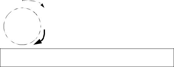
rotation - 5.2
Note: A ’torque’ and ’moment’ are equivalent in terms of calculations. The main difference is that ’torque’ normally refers to a rotating moment.
Given the initial state of a rotating mass, find the state 5 seconds later.
θ 0 = 1rad |
ω 0 |
= 2 |
rad |
α |
= 3 |
rad |
|
-------- |
-------- |
||||||
|
|
|
s |
|
|
s |
2 |
|
|
|
|
|
|
|
|
ans. θ ( 5) |
= 86rad |
|
ω ( 5) |
|
rad |
= 17 |
-------- |
|
s |
||
Figure 5.2 Drill problem: Find the position with the given conditions
5.2 MODELING
Free Body Diagrams (FBDs) are required when analyzing rotational systems, as they were for translating systems. The force components normally considered in a rotational system include,
•inertia - opposes acceleration and deceleration
•springs - resist deflection
•dampers - oppose velocity
•levers - rotate small angles
•gears and belts - change rotational speeds and torques
rotation - 5.3
5.2.1 Inertia
When unbalanced torques are applied to a mass it will begin to accelerate, in rotation. The sum of applied torques is equal to the inertia forces shown in Figure 5.3.
|
θ ,ω α, |
|
∑T = JMα |
(6) |
||
|
|
|||||
|
|
|
||||
|
|
|
(7) |
|||
|
|
JM = Ixx + Iyy |
||||
|
|
|
|
2 |
(8) |
|
J |
I |
xx |
= ∫y dM |
|||
|
||||||
|
2 |
|
||||
|
|
|
|
(9) |
||
|
T |
Iyy = ∫x dM |
||||
|
|
|||||
Note: The ’mass’ moment of inertia will be used when dealing with acceleration of a mass. Later we will use the ’area’ moment of inertia for torsional springs.
Figure 5.3 Summing moments and angular inertia
The mass moment of inertia determines the resistance to acceleration. This can be calculated using integration, or found in tables. When dealing with rotational acceleration it is important to use the mass moment of inertia, not the area moment of inertia.
The center of rotation for free body rotation will be the centroid. Moment of inertia values are typically calculated about the centroid. If the object is constrained to rotate about some point, other than the centroid, the moment of inertia value must be recalculated. The parallel axis theorem provides the method to shift a moment of inertia from a centroid to an arbitrary center of rotation, as shown in Figure 5.4.

rotation - 5.4
JM = J˜M + Mr2 where,
JM = mass moment about the new point
J˜ |
= mass moment about the center of mass |
M |
|
M = mass of the object |
|
r = |
distance from the centroid to the new point |
Figure 5.4 Parallel axis theorem for shifting a mass moment of inertia
JA = J˜A + Ar2
where,
JA = area moment about the new point
J˜A = area moment about the centroid
A = mass of the object
r = distance from the centroid to the new point
Figure 5.5 Parallel axis theorem for shifting a area moment of inertia
Aside: If forces do not pass through the center of an object, it will rotate. If the object is made of a homogeneous material, the area and volume centroids can be used as the center. If the object is made of different materials then the center of mass should be used for the center. If the gravity varies over the length of the (very long) object then the center of gravity should be used.
An example of calculating a mass moment of inertia is shown in Figure 5.6. In this problem the density of the material is calculated for use in the integrals. The integrals are then developed using slices for the integration element dM. The integrals for the moments about the x and y axes, are then added to give the polar moment of inertia. This is then shifted from the centroid to the new axis using the parallel axis theorem.
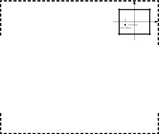
rotation - 5.5
The rectangular shape to the right is constrained to rotate about point A. The total mass of the object is 10kg. The given dimensions are in meters. Find the mass moment of inertia.
First find the density and calculate the moments of inertia about the centroid.
|
ρ |
|
|
10Kg |
|
–2 |
|
= |
------------------------------- |
= 0.125Kgm |
|
||
|
2 |
( 5m) 2( 4m) |
|
|||
|
|
|
|
|
||
|
4 |
-5 |
-2.5 |
5 |
|
|
-1 |
|
-4 |
|
|
|
4 |
2 |
|
|
|
|
|
4 |
|
2 |
|
|
|
|
|
|
–1 y |
3 |
|
4 |
|
||
|
|
|
|
|
|
|
|
|
|
|
|
|
|
|
|
|
|||||||||
|
|
|
|
|
|
|
|
|
|
|
|
|
|
|
|
|
|
||||||||
|
Ixx |
= |
∫ |
y |
dM = |
∫ |
y |
|
ρ |
2( 5m) dy = |
1.25Kgm |
|
---- |
|
|
|
|||||||||
|
|
|
|
|
|
||||||||||||||||||||
|
|
|
–4 |
|
|
|
|
|
|
–4 |
|
|
|
|
|
|
|
|
|
3 |
|
–4 |
|
||
|
|
|
|
|
|
|
|
|
|
|
|
|
|
|
|
|
|
|
|
||||||
|
|
= 1.25Kgm |
–1 |
|
( 4m) 3 |
( –4m) 3 |
= 53.33Kgm |
2 |
|
|
|||||||||||||||
|
|
|
|
||||||||||||||||||||||
|
|
|
|
||||||||||||||||||||||
|
|
|
|
||||||||||||||||||||||
|
|
|
-------------- |
– ----------------- |
|
|
|
|
|||||||||||||||||
|
|
|
5 |
2 |
|
|
|
|
|
5 |
3 |
2 |
|
|
3 |
|
|
–1 x |
3 |
|
5 |
|
|
|
|
|
|
|
|
|
|
|
|
|
|
|
|
|
|
|
|||||||||||
|
|
|
|
|
|
|
|
|
|
|
|
|
|
|
|
|
|
|
|||||||
|
|
|
|
|
|
|
|
|
|
|
|
|
|
|
|
|
|
|
|||||||
|
|
|
|
|
|
|
|
|
|
|
|
|
|
|
|
|
|
|
|
||||||
|
Iyy |
= |
∫ |
x |
dM = |
∫ |
x |
|
ρ |
2( 4m) dx = |
1Kgm |
---- |
|
|
|
|
|
|
|||||||
|
|
|
|
|
|
|
|
||||||||||||||||||
|
|
|
–5 |
|
|
|
|
|
|
–5 |
|
|
|
|
|
|
|
3 |
|
–5 |
|
|
|
||
|
|
|
|
|
|
–1 |
|
( 5m) 3 |
|
( –5m) 3 |
|
|
|
2 |
|
|
|
|
|
|
|||||
|
|
|
|
|
|
|
|
|
|
|
|
|
|
|
|||||||||||
|
|
|
|
|
|
|
|
|
|
|
|
|
|
|
|||||||||||
|
= 1Kgm |
|
|
-------------- |
– ----------------- |
= 83.33Kgm |
|
|
|
|
|
|
|
||||||||||||
|
|
|
|
|
|
|
|
|
3 |
|
|
|
3 |
|
|
|
|
|
|
|
|
|
|
|
|
|
JM |
= Ixx + Iyy |
= 53.33Kgm2 + 83.33Kgm2 |
= 136.67Kgm2 |
|
||||||||||||||||||||
|
|
||||||||||||||||||||||||
|
|
||||||||||||||||||||||||
|
|
||||||||||||||||||||||||
|
|
||||||||||||||||||||||||
|
|
|
|
|
|
|
|
|
|
|
|
|
|
|
|
|
|
|
|
|
|
|
|
|
|
The centroid can now be shifted to the center of rotation using the parallel axis theorem.
JM = J˜M + Mr2 = 136.67Kgm2 + ( 10Kg) ( ( –2.5m) 2 + ( –1m) 2) = 209.2Kgm2
Figure 5.6 Mass moment of inertia example
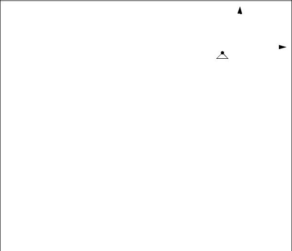
rotation - 5.6
The rectangular shape to the right is constrained to rotate about |
|
|
|
|
|
|
|
|
point A. The total mass of the object is 10kg. The given |
|
|
|
|
|
|
|
|
dimensions are in meters. Find the mass moment of inertia |
|
|
|
4 |
|
|
||
WITHOUT using the parallel axis theorem. |
-2.5 |
|
|
|
|
|||
-5 |
|
|
|
|
|
5 |
||
|
|
|
|
|
|
|||
|
|
|
|
|
|
|
|
|
|
|
|
|
|
|
-1 |
|
|
|
|
|
|
|
||||
|
|
|
|
|
|
|
|
|
|
|
|
|
|
-4 |
|
||
|
|
|
|
|
|
|
|
|
|
ans. |
= 66.33Kgm2 |
|
IMx |
|
|
IMy |
= 145.8Kgm2 |
|
JM = 209.2Kgm2 |
|
Figure 5.7 Drill problem: Mass moment of inertia calculation |
|
|