

- •1. INTRODUCTION
- •1.1 BASIC TERMINOLOGY
- •1.2 EXAMPLE SYSTEM
- •1.3 SUMMARY
- •1.4 PRACTICE PROBLEMS
- •2. TRANSLATION
- •2.1 INTRODUCTION
- •2.2 MODELING
- •2.2.1 Free Body Diagrams
- •2.2.2 Mass and Inertia
- •2.2.3 Gravity and Other Fields
- •2.2.4 Springs
- •2.2.5 Damping and Drag
- •2.2.6 Cables And Pulleys
- •2.2.7 Friction
- •2.2.8 Contact Points And Joints
- •2.3 SYSTEM EXAMPLES
- •2.4 OTHER TOPICS
- •2.5 SUMMARY
- •2.6 PRACTICE PROBLEMS
- •2.7 PRACTICE PROBLEM SOLUTIONS
- •2.8 ASSIGNMENT PROBLEMS
- •3. ANALYSIS OF DIFFERENTIAL EQUATIONS
- •3.1 INTRODUCTION
- •3.2 EXPLICIT SOLUTIONS
- •3.3 RESPONSES
- •3.3.1 First-order
- •3.3.2 Second-order
- •3.3.3 Other Responses
- •3.4 RESPONSE ANALYSIS
- •3.5 NON-LINEAR SYSTEMS
- •3.5.1 Non-Linear Differential Equations
- •3.5.2 Non-Linear Equation Terms
- •3.5.3 Changing Systems
- •3.6 CASE STUDY
- •3.7 SUMMARY
- •3.8 PRACTICE PROBLEMS
- •3.9 PRACTICE PROBLEM SOLUTIONS
- •3.10 ASSIGNMENT PROBLEMS
- •4. NUMERICAL ANALYSIS
- •4.1 INTRODUCTION
- •4.2 THE GENERAL METHOD
- •4.2.1 State Variable Form
- •4.3 NUMERICAL INTEGRATION
- •4.3.1 Numerical Integration With Tools
- •4.3.2 Numerical Integration
- •4.3.3 Taylor Series
- •4.3.4 Runge-Kutta Integration
- •4.4 SYSTEM RESPONSE
- •4.4.1 Steady-State Response
- •4.5 DIFFERENTIATION AND INTEGRATION OF EXPERIMENTAL DATA
- •4.6 ADVANCED TOPICS
- •4.6.1 Switching Functions
- •4.6.2 Interpolating Tabular Data
- •4.6.3 Modeling Functions with Splines
- •4.6.4 Non-Linear Elements
- •4.7 CASE STUDY
- •4.8 SUMMARY
- •4.9 PRACTICE PROBLEMS
- •4.10 PRACTICE PROBLEM SOLUTIONS
- •4.11 ASSIGNMENT PROBLEMS
- •5. ROTATION
- •5.1 INTRODUCTION
- •5.2 MODELING
- •5.2.1 Inertia
- •5.2.2 Springs
- •5.2.3 Damping
- •5.2.4 Levers
- •5.2.5 Gears and Belts
- •5.2.6 Friction
- •5.2.7 Permanent Magnet Electric Motors
- •5.3 OTHER TOPICS
- •5.4 DESIGN CASE
- •5.5 SUMMARY
- •5.6 PRACTICE PROBLEMS
- •5.7 PRACTICE PROBLEM SOLUTIONS
- •5.8 ASSIGNMENT PROBLEMS
- •6. INPUT-OUTPUT EQUATIONS
- •6.1 INTRODUCTION
- •6.2 THE DIFFERENTIAL OPERATOR
- •6.3 INPUT-OUTPUT EQUATIONS
- •6.3.1 Converting Input-Output Equations to State Equations
- •6.3.2 Integrating Input-Output Equations
- •6.4 DESIGN CASE
- •6.5 SUMMARY
- •6.6 PRACTICE PROBLEMS
- •6.7 PRACTICE PROBLEM SOLUTIONS
- •6.8 ASSGINMENT PROBLEMS
- •6.9 REFERENCES
- •7. ELECTRICAL SYSTEMS
- •7.1 INTRODUCTION
- •7.2 MODELING
- •7.2.1 Resistors
- •7.2.2 Voltage and Current Sources
- •7.2.3 Capacitors
- •7.2.4 Inductors
- •7.2.5 Op-Amps
- •7.3 IMPEDANCE
- •7.4 EXAMPLE SYSTEMS
- •7.5 ELECTROMECHANICAL SYSTEMS - MOTORS
- •7.5.1 Permanent Magnet DC Motors
- •7.5.2 Induction Motors
- •7.5.3 Brushless Servo Motors
- •7.6 FILTERS
- •7.7 OTHER TOPICS
- •7.8 SUMMARY
- •7.9 PRACTICE PROBLEMS
- •7.10 PRACTICE PROBLEM SOLUTIONS
- •7.11 ASSIGNMENT PROBLEMS
- •8. FEEDBACK CONTROL SYSTEMS
- •8.1 INTRODUCTION
- •8.2 TRANSFER FUNCTIONS
- •8.3 CONTROL SYSTEMS
- •8.3.1 PID Control Systems
- •8.3.2 Manipulating Block Diagrams
- •8.3.3 A Motor Control System Example
- •8.3.4 System Error
- •8.3.5 Controller Transfer Functions
- •8.3.6 Feedforward Controllers
- •8.3.7 State Equation Based Systems
- •8.3.8 Cascade Controllers
- •8.4 SUMMARY
- •8.5 PRACTICE PROBLEMS
- •8.6 PRACTICE PROBLEM SOLUTIONS
- •8.7 ASSIGNMENT PROBLEMS
- •9. PHASOR ANALYSIS
- •9.1 INTRODUCTION
- •9.2 PHASORS FOR STEADY-STATE ANALYSIS
- •9.3 VIBRATIONS
- •9.4 SUMMARY
- •9.5 PRACTICE PROBLEMS
- •9.6 PRACTICE PROBLEM SOLUTIONS
- •9.7 ASSIGNMENT PROBLEMS
- •10. BODE PLOTS
- •10.1 INTRODUCTION
- •10.2 BODE PLOTS
- •10.3 SIGNAL SPECTRUMS
- •10.4 SUMMARY
- •10.5 PRACTICE PROBLEMS
- •10.6 PRACTICE PROBLEM SOLUTIONS
- •10.7 ASSIGNMENT PROBLEMS
- •10.8 LOG SCALE GRAPH PAPER
- •11. ROOT LOCUS ANALYSIS
- •11.1 INTRODUCTION
- •11.2 ROOT-LOCUS ANALYSIS
- •11.3 SUMMARY
- •11.4 PRACTICE PROBLEMS
- •11.5 PRACTICE PROBLEM SOLUTIONS
- •11.6 ASSIGNMENT PROBLEMS
- •12. NONLINEAR SYSTEMS
- •12.1 INTRODUCTION
- •12.2 SOURCES OF NONLINEARITY
- •12.3.1 Time Variant
- •12.3.2 Switching
- •12.3.3 Deadband
- •12.3.4 Saturation and Clipping
- •12.3.5 Hysteresis and Slip
- •12.3.6 Delays and Lags
- •12.4 SUMMARY
- •12.5 PRACTICE PROBLEMS
- •12.6 PRACTICE PROBLEM SOLUTIONS
- •12.7 ASIGNMENT PROBLEMS
- •13. ANALOG INPUTS AND OUTPUTS
- •13.1 INTRODUCTION
- •13.2 ANALOG INPUTS
- •13.3 ANALOG OUTPUTS
- •13.4 NOISE REDUCTION
- •13.4.1 Shielding
- •13.4.2 Grounding
- •13.5 CASE STUDY
- •13.6 SUMMARY
- •13.7 PRACTICE PROBLEMS
- •13.8 PRACTICE PROBLEM SOLUTIONS
- •13.9 ASSIGNMENT PROBLEMS
- •14. CONTINUOUS SENSORS
- •14.1 INTRODUCTION
- •14.2 INDUSTRIAL SENSORS
- •14.2.1 Angular Displacement
- •14.2.1.1 - Potentiometers
- •14.2.2 Encoders
- •14.2.2.1 - Tachometers
- •14.2.3 Linear Position
- •14.2.3.1 - Potentiometers
- •14.2.3.2 - Linear Variable Differential Transformers (LVDT)
- •14.2.3.3 - Moire Fringes
- •14.2.3.4 - Accelerometers
- •14.2.4 Forces and Moments
- •14.2.4.1 - Strain Gages
- •14.2.4.2 - Piezoelectric
- •14.2.5 Liquids and Gases
- •14.2.5.1 - Pressure
- •14.2.5.2 - Venturi Valves
- •14.2.5.3 - Coriolis Flow Meter
- •14.2.5.4 - Magnetic Flow Meter
- •14.2.5.5 - Ultrasonic Flow Meter
- •14.2.5.6 - Vortex Flow Meter
- •14.2.5.7 - Positive Displacement Meters
- •14.2.5.8 - Pitot Tubes
- •14.2.6 Temperature
- •14.2.6.1 - Resistive Temperature Detectors (RTDs)
- •14.2.6.2 - Thermocouples
- •14.2.6.3 - Thermistors
- •14.2.6.4 - Other Sensors
- •14.2.7 Light
- •14.2.7.1 - Light Dependant Resistors (LDR)
- •14.2.8 Chemical
- •14.2.8.2 - Conductivity
- •14.2.9 Others
- •14.3 INPUT ISSUES
- •14.4 SENSOR GLOSSARY
- •14.5 SUMMARY
- •14.6 REFERENCES
- •14.7 PRACTICE PROBLEMS
- •14.8 PRACTICE PROBLEM SOLUTIONS
- •14.9 ASSIGNMENT PROBLEMS
- •15. CONTINUOUS ACTUATORS
- •15.1 INTRODUCTION
- •15.2 ELECTRIC MOTORS
- •15.2.1 Basic Brushed DC Motors
- •15.2.2 AC Motors
- •15.2.3 Brushless DC Motors
- •15.2.4 Stepper Motors
- •15.2.5 Wound Field Motors
- •15.3 HYDRAULICS
- •15.4 OTHER SYSTEMS
- •15.5 SUMMARY
- •15.6 PRACTICE PROBLEMS
- •15.7 PRACTICE PROBLEM SOLUTIONS
- •15.8 ASSIGNMENT PROBLEMS
- •16. MOTION CONTROL
- •16.1 INTRODUCTION
- •16.2 MOTION PROFILES
- •16.2.1 Velocity Profiles
- •16.2.2 Position Profiles
- •16.3 MULTI AXIS MOTION
- •16.3.1 Slew Motion
- •16.3.1.1 - Interpolated Motion
- •16.3.2 Motion Scheduling
- •16.4 PATH PLANNING
- •16.5 CASE STUDIES
- •16.6 SUMMARY
- •16.7 PRACTICE PROBLEMS
- •16.8 PRACTICE PROBLEM SOLUTIONS
- •16.9 ASSIGNMENT PROBLEMS
- •17. LAPLACE TRANSFORMS
- •17.1 INTRODUCTION
- •17.2 APPLYING LAPLACE TRANSFORMS
- •17.2.1 A Few Transform Tables
- •17.3 MODELING TRANSFER FUNCTIONS IN THE s-DOMAIN
- •17.4 FINDING OUTPUT EQUATIONS
- •17.5 INVERSE TRANSFORMS AND PARTIAL FRACTIONS
- •17.6 EXAMPLES
- •17.6.2 Circuits
- •17.7 ADVANCED TOPICS
- •17.7.1 Input Functions
- •17.7.2 Initial and Final Value Theorems
- •17.8 A MAP OF TECHNIQUES FOR LAPLACE ANALYSIS
- •17.9 SUMMARY
- •17.10 PRACTICE PROBLEMS
- •17.11 PRACTICE PROBLEM SOLUTIONS
- •17.12 ASSIGNMENT PROBLEMS
- •17.13 REFERENCES
- •18. CONTROL SYSTEM ANALYSIS
- •18.1 INTRODUCTION
- •18.2 CONTROL SYSTEMS
- •18.2.1 PID Control Systems
- •18.2.2 Analysis of PID Controlled Systems With Laplace Transforms
- •18.2.3 Finding The System Response To An Input
- •18.2.4 Controller Transfer Functions
- •18.3.1 Approximate Plotting Techniques
- •18.4 DESIGN OF CONTINUOUS CONTROLLERS
- •18.5 SUMMARY
- •18.6 PRACTICE PROBLEMS
- •18.7 PRACTICE PROBLEM SOLUTIONS
- •18.8 ASSIGNMENT PROBLEMS
- •19. CONVOLUTION
- •19.1 INTRODUCTION
- •19.2 UNIT IMPULSE FUNCTIONS
- •19.3 IMPULSE RESPONSE
- •19.4 CONVOLUTION
- •19.5 NUMERICAL CONVOLUTION
- •19.6 LAPLACE IMPULSE FUNCTIONS
- •19.7 SUMMARY
- •19.8 PRACTICE PROBLEMS
- •19.9 PRACTICE PROBLEM SOLUTIONS
- •19.10 ASSIGNMENT PROBLEMS
- •20. STATE SPACE ANALYSIS
- •20.1 INTRODUCTION
- •20.2 OBSERVABILITY
- •20.3 CONTROLLABILITY
- •20.4 OBSERVERS
- •20.5 SUMMARY
- •20.6 PRACTICE PROBLEMS
- •20.7 PRACTICE PROBLEM SOLUTIONS
- •20.8 ASSIGNMENT PROBLEMS
- •20.9 BIBLIOGRAPHY
- •21. STATE SPACE CONTROLLERS
- •21.1 INTRODUCTION
- •21.2 FULL STATE FEEDBACK
- •21.3 OBSERVERS
- •21.4 SUPPLEMENTAL OBSERVERS
- •21.5 REGULATED CONTROL WITH OBSERVERS
- •21.7 LINEAR QUADRATIC GAUSSIAN (LQG) COMPENSATORS
- •21.8 VERIFYING CONTROL SYSTEM STABILITY
- •21.8.1 Stability
- •21.8.2 Bounded Gain
- •21.9 ADAPTIVE CONTROLLERS
- •21.10 OTHER METHODS
- •21.10.1 Kalman Filtering
- •21.11 SUMMARY
- •21.12 PRACTICE PROBLEMS
- •21.13 PRACTICE PROBLEM SOLUTIONS
- •21.14 ASSIGNMENT PROBLEMS
- •22. SYSTEM IDENTIFICATION
- •22.1 INTRODUCTION
- •22.2 SUMMARY
- •22.3 PRACTICE PROBLEMS
- •22.4 PRACTICE PROBLEM SOLUTIONS
- •22.5 ASSIGNMENT PROBLEMS
- •23. ELECTROMECHANICAL SYSTEMS
- •23.1 INTRODUCTION
- •23.2 MATHEMATICAL PROPERTIES
- •23.2.1 Induction
- •23.3 EXAMPLE SYSTEMS
- •23.4 SUMMARY
- •23.5 PRACTICE PROBLEMS
- •23.6 PRACTICE PROBLEM SOLUTIONS
- •23.7 ASSIGNMENT PROBLEMS
- •24. FLUID SYSTEMS
- •24.1 SUMMARY
- •24.2 MATHEMATICAL PROPERTIES
- •24.2.1 Resistance
- •24.2.2 Capacitance
- •24.2.3 Power Sources
- •24.3 EXAMPLE SYSTEMS
- •24.4 SUMMARY
- •24.5 PRACTICE PROBLEMS
- •24.6 PRACTICE PROBLEMS SOLUTIONS
- •24.7 ASSIGNMENT PROBLEMS
- •25. THERMAL SYSTEMS
- •25.1 INTRODUCTION
- •25.2 MATHEMATICAL PROPERTIES
- •25.2.1 Resistance
- •25.2.2 Capacitance
- •25.2.3 Sources
- •25.3 EXAMPLE SYSTEMS
- •25.4 SUMMARY
- •25.5 PRACTICE PROBLEMS
- •25.6 PRACTICE PROBLEM SOLUTIONS
- •25.7 ASSIGNMENT PROBLEMS
- •26. OPTIMIZATION
- •26.1 INTRODUCTION
- •26.2 OBJECTIVES AND CONSTRAINTS
- •26.3 SEARCHING FOR THE OPTIMUM
- •26.4 OPTIMIZATION ALGORITHMS
- •26.4.1 Random Walk
- •26.4.2 Gradient Decent
- •26.4.3 Simplex
- •26.5 SUMMARY
- •26.6 PRACTICE PROBLEMS
- •26.7 PRACTICE PROBLEM SOLUTIONS
- •26.8 ASSIGNMENT PROBLEMS
- •27. FINITE ELEMENT ANALYSIS (FEA)
- •27.1 INTRODUCTION
- •27.2 FINITE ELEMENT MODELS
- •27.3 FINITE ELEMENT MODELS
- •27.4 SUMMARY
- •27.5 PRACTICE PROBLEMS
- •27.6 PRACTICE PROBLEM SOLUTIONS
- •27.7 ASSIGNMENT PROBLEMS
- •27.8 BIBLIOGRAPHY
- •28. FUZZY LOGIC
- •28.1 INTRODUCTION
- •28.2 COMMERCIAL CONTROLLERS
- •28.3 REFERENCES
- •28.4 SUMMARY
- •28.5 PRACTICE PROBLEMS
- •28.6 PRACTICE PROBLEM SOLUTIONS
- •28.7 ASSIGNMENT PROBLEMS
- •29. NEURAL NETWORKS
- •29.1 SUMMARY
- •29.2 PRACTICE PROBLEMS
- •29.3 PRACTICE PROBLEM SOLUTIONS
- •29.4 ASSIGNMENT PROBLEMS
- •29.5 REFERENCES
- •30. EMBEDDED CONTROL SYSTEM
- •30.1 INTRODUCTION
- •30.2 CASE STUDY
- •30.3 SUMMARY
- •30.4 PRACTICE PROBLEMS
- •30.5 PRACTICE PROBLEM SOLUTIONS
- •30.6 ASSIGNMENT PROBLEMS
- •31. WRITING
- •31.1 FORGET WHAT YOU WERE TAUGHT BEFORE
- •31.2 WHY WRITE REPORTS?
- •31.3 THE TECHNICAL DEPTH OF THE REPORT
- •31.4 TYPES OF REPORTS
- •31.5 LABORATORY REPORTS
- •31.5.0.1 - An Example First Draft of a Report
- •31.5.0.2 - An Example Final Draft of a Report
- •31.6 RESEARCH
- •31.7 DRAFT REPORTS
- •31.8 PROJECT REPORT
- •31.9 OTHER REPORT TYPES
- •31.9.1 Executive
- •31.9.2 Consulting
- •31.9.3 Memo(randum)
- •31.9.4 Interim
- •31.9.5 Poster
- •31.9.6 Progress Report
- •31.9.7 Oral
- •31.9.8 Patent
- •31.10 LAB BOOKS
- •31.11 REPORT ELEMENTS
- •31.11.1 Figures
- •31.11.2 Graphs
- •31.11.3 Tables
- •31.11.4 Equations
- •31.11.5 Experimental Data
- •31.11.6 Result Summary
- •31.11.7 References
- •31.11.8 Acknowledgments
- •31.11.9 Abstracts
- •31.11.10 Appendices
- •31.11.11 Page Numbering
- •31.11.12 Numbers and Units
- •31.11.13 Engineering Drawings
- •31.11.14 Discussions
- •31.11.15 Conclusions
- •31.11.16 Recomendations
- •31.11.17 Appendices
- •31.11.18 Units
- •31.12 GENERAL WRITING ISSUES
- •31.13 WRITERS BLOCK
- •31.14 TECHNICAL ENGLISH
- •31.15 EVALUATION FORMS
- •31.16 PATENTS
- •32. PROJECTS
- •32.2 OVERVIEW
- •32.2.1 The Objectives and Constraints
- •32.3 MANAGEMENT
- •32.3.1 Timeline - Tentative
- •32.3.2 Teams
- •32.4 DELIVERABLES
- •32.4.1 Conceptual Design
- •32.4.2 EGR 345/101 Contract
- •32.4.3 Progress Reports
- •32.4.4 Design Proposal
- •32.4.5 The Final Report
- •32.5 REPORT ELEMENTS
- •32.5.1 Gantt Charts
- •32.5.2 Drawings
- •32.5.3 Budgets and Bills of Material
- •32.5.4 Calculations
- •32.6 APPENDICES
- •32.6.1 Appendix A - Sample System
- •32.6.2 Appendix B - EGR 345/101 Contract
- •32.6.3 Appendix C - Forms
- •33. ENGINEERING PROBLEM SOLVING
- •33.1 BASIC RULES OF STYLE
- •33.2 EXPECTED ELEMENTS
- •33.3 SEPCIAL ELEMENTS
- •33.3.1 Graphs
- •33.3.2 EGR 345 Specific
- •33.4 SCILAB
- •33.5 TERMINOLOGY
- •34. MATHEMATICAL TOOLS
- •34.1 INTRODUCTION
- •34.1.1 Constants and Other Stuff
- •34.1.2 Basic Operations
- •34.1.2.1 - Factorial
- •34.1.3 Exponents and Logarithms
- •34.1.4 Polynomial Expansions
- •34.1.5 Practice Problems
- •34.2 FUNCTIONS
- •34.2.1 Discrete and Continuous Probability Distributions
- •34.2.2 Basic Polynomials
- •34.2.3 Partial Fractions
- •34.2.4 Summation and Series
- •34.2.5 Practice Problems
- •34.3 SPATIAL RELATIONSHIPS
- •34.3.1 Trigonometry
- •34.3.2 Hyperbolic Functions
- •34.3.2.1 - Practice Problems
- •34.3.3 Geometry
- •34.3.4 Planes, Lines, etc.
- •34.3.5 Practice Problems
- •34.4 COORDINATE SYSTEMS
- •34.4.1 Complex Numbers
- •34.4.2 Cylindrical Coordinates
- •34.4.3 Spherical Coordinates
- •34.4.4 Practice Problems
- •34.5 MATRICES AND VECTORS
- •34.5.1 Vectors
- •34.5.2 Dot (Scalar) Product
- •34.5.3 Cross Product
- •34.5.4 Triple Product
- •34.5.5 Matrices
- •34.5.6 Solving Linear Equations with Matrices
- •34.5.7 Practice Problems
- •34.6 CALCULUS
- •34.6.1 Single Variable Functions
- •34.6.1.1 - Differentiation
- •34.6.1.2 - Integration
- •34.6.2 Vector Calculus
- •34.6.3 Differential Equations
- •34.6.3.1.1 - Guessing
- •34.6.3.1.2 - Separable Equations
- •34.6.3.1.3 - Homogeneous Equations and Substitution
- •34.6.3.2.1 - Linear Homogeneous
- •34.6.3.2.2 - Nonhomogeneous Linear Equations
- •34.6.3.3 - Higher Order Differential Equations
- •34.6.3.4 - Partial Differential Equations
- •34.6.4 Other Calculus Stuff
- •34.6.5 Practice Problems
- •34.7 NUMERICAL METHODS
- •34.7.1 Approximation of Integrals and Derivatives from Sampled Data
- •34.7.3 Taylor Series Integration
- •34.8 LAPLACE TRANSFORMS
- •34.8.1 Laplace Transform Tables
- •34.9 z-TRANSFORMS
- •34.10 FOURIER SERIES
- •34.11 TOPICS NOT COVERED (YET)
- •34.12 REFERENCES/BIBLIOGRAPHY
- •35. A BASIC INTRODUCTION TO ‘C’
- •35.2 BACKGROUND
- •35.3 PROGRAM PARTS
- •35.4 HOW A ‘C’ COMPILER WORKS
- •35.5 STRUCTURED ‘C’ CODE
- •35.7 CREATING TOP DOWN PROGRAMS
- •35.8 HOW THE BEAMCAD PROGRAM WAS DESIGNED
- •35.8.1 Objectives:
- •35.8.2 Problem Definition:
- •35.8.3 User Interface:
- •35.8.3.1 - Screen Layout (also see figure):
- •35.8.3.2 - Input:
- •35.8.3.3 - Output:
- •35.8.3.4 - Help:
- •35.8.3.5 - Error Checking:
- •35.8.3.6 - Miscellaneous:
- •35.8.4 Flow Program:
- •35.8.5 Expand Program:
- •35.8.6 Testing and Debugging:
- •35.8.7 Documentation
- •35.8.7.1 - Users Manual:
- •35.8.7.2 - Programmers Manual:
- •35.8.8 Listing of BeamCAD Program.
- •35.9 PRACTICE PROBLEMS
- •36. UNITS AND CONVERSIONS
- •36.1 HOW TO USE UNITS
- •36.2 HOW TO USE SI UNITS
- •36.3 THE TABLE
- •36.4 ASCII, HEX, BINARY CONVERSION
- •36.5 G-CODES
- •37. ATOMIC MATERIAL DATA
- •37. MECHANICAL MATERIAL PROPERTIES
- •37.1 FORMULA SHEET
- •38. BIBLIOGRAPHY
- •38.1 TEXTBOOKS
- •38.1.1 Slotine and Li
- •38.1.2 VandeVegte
- •39. TOPICS IN DEVELOPMENT
- •39.1 UPDATED DC MOTOR MODEL
- •39.2 ANOTHER DC MOTOR MODEL
- •39.3 BLOCK DIAGRAMS AND UNITS
- •39.4 SIGNAL FLOW GRAPHS
- •39.5 ZERO ORDER HOLD
- •39.6 TORSIONAL DAMPERS
- •39.7 MISC
- •39.8 Nyquist Plot
- •39.9 NICHOLS CHART
- •39.10 BESSEL POLYNOMIALS
- •39.11 ITAE
- •39.12 ROOT LOCUS
- •39.13 LYAPUNOV’S LINEARIZATION METHOD
- •39.14 XXXXX
- •39.15 XXXXX
- •39.16 XXXXX
- •39.17 XXXXX
- •39.18 XXXXX
- •39.19 XXXXX
- •39.20 XXXXX
- •39.21 SUMMARY
- •39.22 PRACTICE PROBLEMS
- •39.23 PRACTICE PROBLEM SOLUTIONS
- •39.24 ASSGINMENT PROBLEMS
- •39.25 REFERENCES
- •39.26 BIBLIOGRAPHY
writing guide - 32.1
32. PROJECTS
32.1
The project is intended to emphasize proper project management and team skills to produce a complex engineering system from concept to completion.
32.2 OVERVIEW
Cranes are used to move large loads in industrial environments. To do this they normally lift a load and then move it to a new position. At the end of the motion the load is put down. If the load is swaying, the operator may have to pause before putting down the load. This delay is undesirable because it increases the total cycle time for the crane.
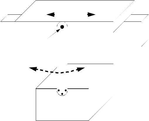
This design project will endeavor to build a proof-of-concept prototype for an antisway system for a gantry crane as shown in Figure 32.1. The crane will ride on a wooden beam constructed with 2x4 lumber (actually smaller). An electric
writing guide - 32.2
motor will drive the cart left or right. The mass will hang below the cart.
motor driven cart
|
|
|
|
|
|
|
|
|
|
|
|
|
|
|
|
|
|
|
|
|
|
|
|
|
|
|
|
|
|
|
|
|
|
|
|
|
|
|
|
|
|
|
|
|
|
|
|
|
|
|
|
pivot point |
|
|
|
|
|
|
|
|
|
|
|
|
|
fixed rail (wood 2x4) |
|
|
|
|
|
|
|
|
|
|
|
|
|
|
|
|
|
|
|
|
|
|
|
|
|
|
|
|
|
|
|
|
|
|
|
1Kg mass
Figure 32.1 The equipment
The system will use active compensation to move the cart between positions, and to move the cart to compensate for swaying of the suspended mass. The overall system performance will be evaluated on how quickly the crane can move the load, and then eliminate sway. Additional factors used in assessment of performance will be the mass, cost and overall design quality.
32.2.1 The Objectives and Constraints
The design will be mounted on 2x4 lumber and controlled through a wire harness to external electronics and power supplies. The apparatus must be easily mounted and removed without damaging the experimental setup. It will be expected to carry a 1Kg mass, suspended 40cm below the top of the 2x4. The 2x4 will be oriented so that the longer dimension is vertical. The mass will be mounted with a carriage bolt that is at least 3 inches long, with a 1/4" diameter. The arm must be able to swing freely, as it is meant to be equivalent to a cable suspending the mass. The mass will be provided with a rod that will be between 1/4" and 1/2". The mass will be a cylinder that is free to rotate to reduce dynamic effects rotation. The width of the mass will be less than or equal to the