

Ceramic Technology and Processing, King
.pdfMilling and Equipment 43
Figure 3.12: Microstructure of SEPR Beads in Polished Section
Figure 3.13: TOSOH Beads (Courtesy of TOSOH)
44 Ceramic Technology and Processing
6.0 MILL RACKS
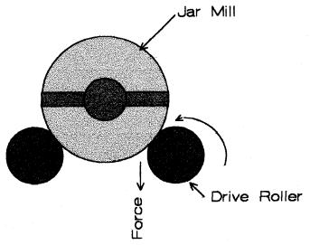
Laboratory jar mills are usually rotated on a mill rack. The rack is a steel frame with two rollers per tier with usually one to three tiers. On each tier, there are two rollers: a drive roller and an idler. The drive roller is usually driven with a chain and sprocket connected to a gear reduction motor. Since mills come in different diameters, it is advantageous to have a variable speed drive and a tachometer for each tier. The drive roller must have a force vector pulling down on the mill body, as shown in Figure 3.14.
Figure 3.14: Mill Roller Direction
Milling and Equipment 45
When the drive roller force vector pulls up, the mill will slip and not roll at the proper speed. The proper speed is 60-70% of the critical speed. As the mill rotates, the grinding media is subjected to two accelerations: gravitational force and centrifugal force. When these are equal or when centrifugal acceleration is the greater, the media will just ride around and not do any grinding. This limiting factor is the critical speed given in the equation below:
a = v2/r |
(3.1) |
Where a is the acceleration due to rotation, v is the velocity around the mill's internal diameter (ID), and r is the mill's ID. In most labs, there are mills of different internal diameters, therefore the mention of a variable speed drive. For each diameter, there will be an optimum rack speed. In design, there are six important factors: a gear ratio of the mechanism, a gear motor in the right speed range, a variable speed drive, a separate speed control for each tier, a tachometer for each tier, and a timer for each tier. The idler roller should be adjustable laterally to accommodate different diameter mills. Commercial mill racks usually do not have all these features, but they can be added if requested.
There are two types of rollers: steel and rubber. For the mill to rotate properly, there should be enough friction to turn the mill body. Rubber against steel is satisfactory, where either the rubber or the steel can be on the mill or on the roller. Steel does not have enough friction against either rigid polymers or itself to turn the mill. Rubber rollers are available with molded on-end flanges that are a great help to keep the mill on the rack. Jar mills will always migrate to the end of the rack, where they will fall off without the flanges or other restraining mechanisms.
With more than one mill on the rack, the jar mills will all migrate to one end and will rub against each other. As a result, either the closure mechanism on one mill can flip the other off the rack, or the closure on one mill can unscrew the closure on the other. If this occurs, the batch will spill over the mill-rack, onto the lower tiers, and onto the floor where it will harden. This in not an uncommon phenomenon as the jar mill diameters are different, causing the end closures to get entangled. Additionally, the mills are rotating at different centers and at different speeds; causing the closure screw to unwind, the lid to open and the batch to spill.
46 Ceramic Technology and Processing
The temperature of the mill batch can increase due to the friction in the mill. This in turn will cause the internal pressure to increase and possibly cause the batch to leak out of the mill.
Since each ceramist's experimental needs vary, multiple users can further complicate the management of these problems. These problems are manageable if only one person uses the mill rack at a time.
There is an additional problem associated with the jar mills. Layers of dried slip can build up on the lid, gasket, and top of the mill body. This buildup makes it difficult to maintain a leak-proof seal. Additionally, as the bolt in the cross bar clamp is repeatedly tightened, the cross bar bends into an arc and no longer fits the ears on the mill-body. This in turn can cause the slip to spill. Keep the lid, gasket, and top of the mill body clean. Hardened slip can be hard to remove and a scraper is often needed.
To obtain the desired particle size, the milling time is specified. Any change in that time will produce a different particle size distribution with a coarser size when the time is shorter and a finer size when the time is longer. Problems arise whenever there is a power failure or when someone turns off the mill rack to remove a mill. With the mill rack off, the time is compromised. It is not so bad if this is evident, but it is a serious problem when not evident. There has to be an understanding among people using the mill rack that the speed cannot be changed or the rack left off other than momentarily when someone else has a mill running. It would be wise to measure the particle size distribution. If it the particle size is not reasonable, one should start over.
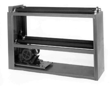
A commercial mill rack is shown in Figure 3.15 (Courtesy of E.R. Advanced Ceramics). This mill rack has a variable speed, but the speed is the same for both tiers. This is not a problem provided the mills are all of the same diameters.
Milling and Equipment 47
Figure 3.15: Commercial Mill Rack
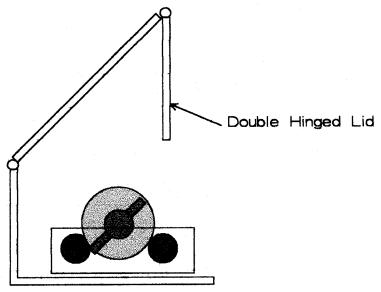
Mill racks are noisy and are generally placed in an enclosure with a door in front. A mill enclosure helps reduce noise that emanates from the mill rack, but it also makes it difficult to clean the spills and to move the mill due to its weight. Figure 3.16 is a schematic of such an enclosure.4
The enclosure is shown for a single tier. Since the lid on the enclosure is double hinged, it is lifted away providing easy access to the rack and a better angle. This enables one to lift the mill using one's legs and not one's back.
48 Ceramic Technology and Processing
Figure 3.16: Mill Rack Enclosure
7.0 OTHER MILL DESIGNS
Some mill designs will not be discussed as they are not usually seen in the ceramic laboratory. These mills are too large for lab use, the batch can be easily contaminated, and clean up is very difficult. In a plant, the mills repeatedly run the same formulation and clean up is not a problem, but clean up is essential in the lab as many different formulations are used. The following five mill types will be discussed: attritors, stirred mills, vibrating mills, planetary mills, and jet mills.
Milling and Equipment 49
Attritors
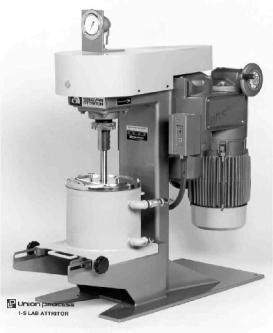
Attritors have a cylindrical shell that can be lined with wearresistant materials and a rotating vertical impeller. The impeller has cross bars that can be covered with wear-resistant, ceramic sleeves. The attritor is filled about two-thirds full with the grinding media. All stirred mills should use a spherical media as other media shapes tend to over pack and overload the drive. Stirred mills are much more energetic than ball mills; as such, milling times are reduced. Seals and bearings are up out of the batch creating a maintenance advantage. Attritors can be operated in three modes: batch, recirculating, and continuous sometimes in series. Most lab work uses the batch mode as shown in Figure 3.17 (Courtesy of Union Process)
Figure 3.17: Attritor (Courtesy of Union Process.)
50 Ceramic Technology and Processing
Stirred Mills
The stirred mills, like the attritors, have a grinding media agitated with a mechanism such as an impeller or a rotating cylinder. Some of these mills have a horizontal impeller that places the seals and bearings into the batch. Some stainless steel impellers wear and contaminate the batch. Milling equipment develops and evolves so fast that this discussion will likely be obsolete by the time it is read. Nevertheless, the principles will have a longer lasting value.
Epworth Manufacturing Company
A horizontal stainless shaft places the seals and bearings into the batch and the stainless wear. This is a high intensity mill that requires a minimal amount of media.
Welte RS Pulversizer
The rotating cylindrical part can be coated with a wear-resistant surface. Seals and bearings are up out of the mix. This mill has minimal media requirements, and wear resistant liners can be used.
Netzsch Small Media Mills
These mills provide options on the mechanical action and minimize media requirements. Milling is done in an annulus with the media. The rotor is horizontal and places the bearings in the mix; however, a mechanical seal keeps the seals flushed.
Milling and Equipment 51
Turbomill
This Turbomill has a rotating slotted cylindrical cage that is constructed of high density polyethylene.5 Since the cage wears during milling, it adds a considerable amount of polymeric contamination to the batch. The cage is vertical; hence, the seals and bearings are down in the mix.
Cyclomill
This Cyclomill design is experimental; it is included here as it may have novel advantages.6 The mill gyrates rather than rotates. To visualize the motion, think of a Ferris wheel but substitute the chairs with cylindrical, grinding vessels. An increase in the gravitational force is due to the gyration. A potential advantage is that there are no seals or bearings in the mix. With the use of flexible tubing, the mill can be set up for continuous grinding. The mill can also be lined, and it uses a modest quantity of grinding media.
The stirred mills grind faster than ball mills. Additionally, they use less of the grinding media. (This is an issue as high quality media are expensive.) The 2-3 mm diameter, TZP spheres are preferred in many cases. Most stirred mills are water jacketed to disperse the heat. Without a heat dispersal mechanism, one could overheat the binder.
Vibratory Mills
Vibratory mills usually consist of annular-shaped tubs mounted on a shaker base.7 The tub is about two-thirds full of a grinding medium that can be spherical or cylindrical. Cylinders with rounded ends and with 1-1.5 cm diameters are commonly available. An adjustable, off-balanced rotor imposes the vibration. One can use a batch mode or a circulating mode of operation, though the batch mode is commonly used in the lab. To
52 Ceramic Technology and Processing
minimize contamination, the tub can be lined with a polymer lining. The milling intensity is moderate and is somewhere between the intensity of the ball and stirred mills. Vibratory mills are good choices for pure ceramic powders due to the high purity media and the low wear rate. In one test, MgO stabilized zirconia showed a high wear rate; it added 1-2% ZrO2 to a Bayer alumina batch during milling. This illustrates that the wear rate of the media can be very important.
Planetary Mills
Planetary mills usually consist of four, small, balanced mills in a planetary array. This setup helps achieve higher gravitational forces that help shorten the grinding time. Gearing imparts two rotary motions: around the central axis and around the axis of each smaller mill. For some reason, these mills are not found in many laboratories. It could be because of the four small mills that have to be batched, balanced, and cleaned.
Mill Clean Up
For purposes of this discussion, one assumes that the type of application selected is contingent on minimizing contamination. Of course, this is not always true. One should also consider what is more appropriately necessary in achieving the required result.
Cleaning the Milling Media
Empty the contents of the jar mill onto a screen placed over a container. Vibration will enhance recovery of the slip as most slips are pseudoplastic. One can construct a rig to hold both the screen and slip receptacle on the vibrator. When dealing with viscous slips, spray a mist of water onto the grinding media to help recover the additional slip. The screen