

Ceramic Technology and Processing, King
.pdfForming 193
the mold surface. Drying shrinkage is obtained by casting a slip that is just a little bit flocculated.
- Split Molds are often used especially for platey shapes as shown in Figure 6.37.
Figure 6.37: Split Mold. Molds separating along the body diagonal provide release of the cast part.
This view is simplistic. A photograph of a split mold was shown earlier. The idea here is to design the mold so that the part is free to release. Here, the split is along the body diagonal. A cylindrical mold is split in half along its axis. The two halves have to fit together correctly as previously shown by using interlocks. In a ceramics lab, the molds are generally simple, but sometimes it is necessary to become more complicated.
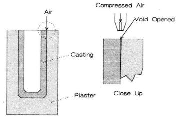
Compressed air. A mold with air channels was shown earlier. One can use compressed air in other ways to help release of the part. One way is to place an air nozzle at the interface between the plaster and the casting. Air under pressure can break the part loose and release it. This is shown schematically in Figure 6.38.
194 Ceramic Technology and Processing
Figure 6.38: Air Release. Placing an air jet on the edge of the cast part can help to obtain release.
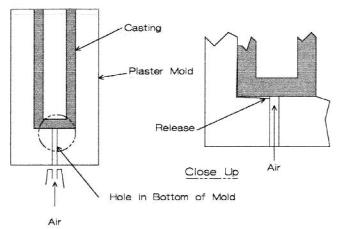
A better way is to drill a small hole in the bottom of the mold, intersecting the die cavity. When casting, the hole will fill with slip and cast. A piece of tape on the bottom of the hole will prevent the slip from running out at the start. Figure 6.39 depicts such a mold.
The part is forced out of the mold with air pressure that can cause it to become ballistic, so it is a good idea to catch it before it gets away. Also, turn the air pressure down just sufficient to break the part free.
Forming 195
Figure 6.39: Bottom Hole in Mold. Compressed air entering the mold at the base pushes the casting out of the mold.
Corn starch. When there is adhesion between the plaster and the cast, a release film on the mold cavity can solve the problem. Pour a dilute water suspension of corn starch into the mold for three to five seconds before pouring it out. This leaves a thin layer of starch on the mold wall. Unless heated, starch will remain as particles, so the coating is a permeable film. This procedure will not address all of the mold release problems, but it can help to eliminate adhesion. When the part is fired, the starch burns off cleanly.
A suspension of starch and water is very dilatant in a highly loaded concentration. This is an easy demonstration of dilatant rheology.
196 Ceramic Technology and Processing
Timing. Sometimes, there is an optimum casting time when the part should be demolded. There are two conditions: drying shrinkage and enough rigidity for the part to be self supporting. The part will not dry uniformly while it is still in the mold. The preferred technique is to release the part when possible consistent with rigidity. Use of a plaster core creates a compilation in that the casting will shrink onto the plaster core and put the part in tension, perhaps cracking it. One needs to have experience to determine the optimum demolding time for each case. There may be a problem with a system; however, one can get lucky and not have to worry excessively about timing.
Fuel Oil.10 A thin coating of fuel oil rubbed onto the casting surface can sometimes prevent sticking. When all else fails, beat the bottom of the mold with a rubber mallet. Sometimes, this will jar the part loose, but often it will chip the plaster mold.
Check List, Slip Casting
•Adjust the plaster moisture.
•Measure casting rate and adjust flocculation.
•Pour the slip down the side.
•Determine demolding time.
•Rectify problems, refer to text.
•Measure drying and firing shrinkages.
7.0RELATED CASTING PROCEDURES
There are other methods for consolidating slips into parts. Each has advantages and disadvantages.
Forming 197
Pressure Casting
Pressure casting and filtration casting are closely related. Perhaps the difference is that, in pressure casting, one uses plaster as the adsorbing medium while, in filtration casting, one uses a porous polymer as the medium or filter. One type of filtration casting has been patented and is commercially available. Unfortunately, it is necessary to obtain a license before using the method for experimental laboratory purposes. A license requirement is overkill for a lab when one does not know if the process is going to be commercialized.
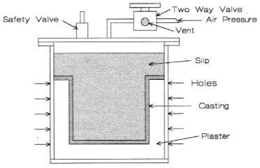
Polymer molds are dedicated to a single shape from which many parts will be cast. Of course, plaster molds are also dedicated to one shape, but they can be easily made in the lab and are a lot cheaper. A sketch of a pressure casting apparatus using a plaster liner is shown in Figure 6.40.
Figure 6.40: Pressure Casting Device. A metal shell has a plaster mold cast inside. Holes are drilled in the shell to provide escape of air. Always include a relief valve for safety.
198 Ceramic Technology and Processing
Explanation: The shell is 0.25 inch thick steel with a welded flange. The lid is a steel disc with threaded holes for the air inlet, vent valve, and the pressure safety valve. Holes were drilled into the shell wall to provide removal of the water during casting. Arrows in the sketch point to these holes. An O-ring seal is at the junction between the lid and flange. Slip is poured into the plaster cavity at a level high enough to furnish a reservoir during casting. One can select the pressure, but 60 psi is prudent and adequate for this design. Casting is substantially faster by using pressure. For example, a 0.25 inch wall for sub-micrometer alumina was built up in about 0.5 hours. More importantly, one can make parts with pressure casting, but this may not be easily feasible by conventional slip casting. Pressure casting can be enabling! One part that can be made is a flanged jar with fired dimensions of 13-cm diameter flanges and 13-cm height. The slip to make this part can have a d50 as small as 0.6 μm.
When thinking about coarse-grained slips where settling is a serious problem, pressure casting can greatly reduce casting time and by that alleviate this problem. One can design apparatus that is not too expensive or difficult to use. Pressure casting deserves much more attention than it is receiving. Let us speculate a little.
Possible Pressure Casting Mold Designs
PVC has tensile strengths as high as 6000-10,000 psi, far more than needed. A length of PVC pipe can be fitted with standard end flanges and plates for top and bottom closures. One can either use drain tubing or use a solid tubing with holes drilled in the sides. Line the tube with a filter that could be plaster. A sketch is shown in Figure 6.41.
Clamp the assembly into place on a casting bench. The casing has holes so that the water can escape. Inside is a layer of a permeable material that either absorbs the water or acts as a filter, but it retains the solid particles. Plaster would be a good place to start. An impervious sleeve at the top prevents casting in that location so that a slip reservoir is maintained. One can pour or pump the slip into the cavity. When pumped, the device does not have air pockets. One can control the pressure by a sensor that activates the pump. As the slip is pressurized, it deposits a layer on the wall that builds up in thickness with time. The casting rate increases

Forming 199
proportionally with the applied pressure, resulting in a shortened casting time. Once the desired wall thickness is obtained, the pressure is released, the toggle clamps are sprung, and the mold and top are removed from the casting bench. Now, the excess slip is drained out and the part partially dried by setting the mold on an air supply that pushes a flow of air through the casting. The same air supply, by increasing the pressure, can pop the casting out of the mold.
Figure 6.41: Pressure Casting Tooling, Speculative. The tooling should be durable and inexpensive.
This above example is for a simple cylindrical shape. There is no reason why one cannot fabricate more complex shapes in the same manner, though this may require a segmented permeable liner to provide release of the part.
Figure 6.41 would have size limitations due to the availability of PVC pipe sizes and the greater stresses on larger sizes. Let us speculate
200 Ceramic Technology and Processing
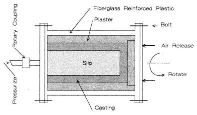
again. Figure 6.42 is a schematic of a hypothetical casting device for a large part, say two feet in diameter.
Figure 6.42: Large Rotary Slip Casting Device, Speculative. The tooling should prevent settling and increase the casting rate.
The shell is fiberglass-reinforced plastic with perforations. End closures are bolted on. Rotation on a horizontal axis at one or two rpm frustrates settling of the coarse particles. The sketch shows the mold filled with slip under pressure. It is very difficult to pump a coarse-grained slip as it will segregate in the pump and supply lines. It would be better to tip the assembly up to a vertical position and pour the slip in directly from the mixer. Then, immediately seal and place the assembly horizontally with rotation.
It is very likely that the plaster will crack when the slip is pressurized. This does not matter, as the slip will fill the cracks and seal them. One can release the large part with compressed air, but again the assembly should be tilted vertical so the part can slip out onto a support
Forming 201
structure. Release will be easier if the plaster mold has a slight taper so that, as a minute amount of release is obtained, the part will slip right out. Since the piece is large and heavy, the assembly is turned upside down and the mold lifted off the casting. Remember, this has not been done and is only a speculation. One can visualize all kinds of things that could go wrong.
All of these speculations along with a little experience is convincing enough that pressure casting is a superior way to cast ceramics and should receive more attention.
T Casting
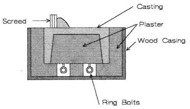
T casting is an abbreviation for thixotropic but this can often be a misnomer. Slips used in T casting are coarse grained and are often pseudoplastic with a high-solids loading. For true T casting, one can use a variety of thixotropic additives. These range from chemically modified clays, hectorite, fumed silica, and organic compounds. Thixotropy often takes an appreciable time to develop in a slip. Clay-based slips can take a few hours for the viscosity to build up. One mostly uses T slips for refractory parts. They have a high-solids loading thus making them dilatant, but this is not desirable from a mixing point of view. One common T casting operation is casting saggers. The slip is kept moving in a mixer and then poured into a vibrating plaster mold that has both an outer body and a core. The sagger is cast bottom side up as shown in Figure 6.43.
The mold is made of plaster with two parts: an outer lining in the wood form and the core that has ring bolts for pulling the core out of the casting. Poplar is a wood of choice for wet applications. One can lacquer the wood with a water-resistant coating such as polyurethane and coat it with a release agent. Since the slip has high-solids loading, removal of just a small amount of water will solidify the part. Vibration lowers the viscosity of the slip when it is pseudoplastic and helps to fill the mold cavity. The base of the sagger is screed off flat. When one stops the vibration, the viscosity increases and the part casts with little settling. It is often convenient to design the wooden case so that it can be dismantled. As this mold has a plaster core, the demolding time is critical because the part
202 Ceramic Technology and Processing
shrinks and could crack. Do not leave until the core is pulled and the part demolded. Once the core starts to come out, the taper causes it to release easily.
Figure 6.43: T Cast tooling for a Sagger.
When there is a true thixotropic mix, the slip will thicken and retard settling of the coarse grain. An important characteristic of T casting is if the viscosity increases quickly after pouring.
Though T casting is a little more labor intensive than other casting methods, but it is still useful.
Centrifugal Casting
Centrifugal casting has been used for a long time in the metals and plastics industries. There is some literature in the ceramics industry.11 The advantages are that it can consolidate a part quickly, can make many parts in one cast, and can make intricate shapes with an appropriate mold. The disadvantages include keeping the apparatus balanced, cost of the